Osawa_Odessa
Banned

- Joined
- Dec 31, 2012
- Messages
- 168
- Helped
- 1
- Reputation
- 2
- Reaction score
- 1
- Trophy points
- 1,298
- Activity points
- 0
Hi,
I am learning about RF power amplifier from a paper "Design of 2.1GHz RF CMOS PowerAmplifierfor 3G". I want to simulate it in Cadence but there are no specific values for components. Now I am wanting to compute value of components and power gain.
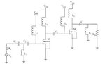
The picture is an RF power amplifier class AB with two stages.
C1, C2, and L1 is an input matching network. The voltage source has resistance Rs = 50Ω. I want to compute values of C1, C2, and L1 but I got stuck.
Could you guide me on this? Thanks.

I am learning about RF power amplifier from a paper "Design of 2.1GHz RF CMOS PowerAmplifierfor 3G". I want to simulate it in Cadence but there are no specific values for components. Now I am wanting to compute value of components and power gain.
The picture is an RF power amplifier class AB with two stages.
C1, C2, and L1 is an input matching network. The voltage source has resistance Rs = 50Ω. I want to compute values of C1, C2, and L1 but I got stuck.
Could you guide me on this? Thanks.