Continue to Site

Welcome to EDAboard.com

Welcome to our site! EDAboard.com is an international Electronics Discussion Forum focused on EDA software, circuits, schematics, books, theory, papers, asic, pld, 8051, DSP, Network, RF, Analog Design, PCB, Service Manuals... and a whole lot more! To participate you need to register. Registration is free. Click here to register now.

how to claculate transistor base resistor

Status
Not open for further replies.

raman00084

Full Member level 6
Joined
Nov 29, 2010
Messages
362
Helped
2
Reputation
4
Reaction score
2
Trophy points
1,298
Activity points
4,006
how to calculate transistor base resistor for load switching application that is
transistor as switch
collector to emitter voltage is 24v

base to emitter voltage is 5v

load current is 1Amps

what value of base resistor i must use, any formula?
 

hi,
A good rule of thumb is to assume the transistor Gain is 10 when used as a switch.

So 1Amp collector current would require 100mA to ensure saturation of Vce.

Ignoring Vbe of 0.7v, thats 24V/100mA =240R

E
 

hi,
A good rule of thumb is to assume the transistor Gain is 10 when used as a switch.

So 1Amp collector current would require 100mA to ensure saturation of Vce.

Ignoring Vbe of 0.7v, thats 24V/100mA =240R

E
i think you made a mistake : its 5/100mA=50 ohm
 

what is 100ma how that value came my base to emitter voltage is 5v and collector to emitter voltage is 24v
 

100 mA is base current required to get Collector current of 1 Amp. What transistor are you using ? Why don't you use SCR ?


Say you need 100 mA base current to get 1 Amp Collector current calculated using Ic = (beta)Ib, Ib = Ic/beta

Now you know required base current. 0.7V is needed to forward bias BE junction abd you have 5V so

(5V - 0.7V) / Ib = Rb

0.7V = Vbe
 
Last edited:

how to find beta value for example the transistor is tip32c


how to take hfe value in tnsistor data sheet there are two hfe min and max which value to use for example let us assume my vcc is 24v used to drive my base as well as my load, if i use 2.2k in the base what is the maximum collector current i will get
generally formula says ib= ic/hfe, in this case what value of hfe i should use my transistor is tip32c

regards
kalyan
 

hi,
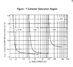
You did say you wanted to use the TIP32 as a Switch, for a Ic =1amp, so it should be biased to ensure Vce saturation, look at the curves on this graph.

A 2k2 Base will not provide enough current to saturate the TIP, so it could get hot!

E
 

Attachments

  • AAesp02.gif
    AAesp02.gif
    29 KB · Views: 60

hi,
Consider the case where the TIP is passing say 1Amp and the Vce is 1.5v [Not completely saturated due to insufficient Base current]

The TIP would have to dissipate 1A * 1.5V = 1.5Watts, and it will heat up.

For an Ic= 3Amp, that would be 4.5Watts and a heat sink would be required.

E
 

for bjt that is tip requires only base current not voltage right. i have a doubt if my vce = 24v and vbe voltage is 2v and capable of delivering 20ma base current then the tip can be fully saturated right and produce 1a output ?
 

The transistor current gain at saturation curves are usually standardized at Ic:Ib ratio of 10:1 for a good reason, which has nothing consistently relevant to the linear hFE or Beta current gain.

Some may be exceptional at 20:1 or 50:1 for the best in Ultra Low Collector-Emitter Saturation Voltage .

Essentially like the technology used in low RdsOn MOSFETs applied to Bipolar junctions transistors, you can select devices with very low Vce_Sat or now called Rce_sat which is the saturated effective series resistance or ESR which exists for any diode or transistor being used as a Switch.

For your personal training scrutinize the specification for this $0.1 part and remember that you can pay extra for "ULtra-Low" Vce-Sat when you need it to reduce power dissipation in a tiny part.

Unless you want to get into Semiconductor Physics and all the patents owned by Diodes Inc (nee Zetex), just accept that it is possible to make them this way with more qualities of low Rce like low RdsOn.

THis means they have much less Miller Capacitance effect but act in current gain mode, unlike MOSFETs which are voltage controlled & require almost no current on or off but huge currents from Miller Capacitance (Cin+Cout) during the transition time only.

Use this as an alternative solution. Very important => Learn to calculate ESR of any diode or saturated transistor from the Vce Saturation curves in old designs such as **broken link removed** and learn to locate the parameters in new transistor designs


Hard to locate but on "MMBT3904" Figure 2, Vce vs Ic @Ic/Ib=10 at the end of the curve the slope is around 1.6 Ohms, whereas on new transistors with "ultra low" Vce(Sat) or equivalent Rce or delta Vce/Ice on Vce sat curves or as I like to call it the ESR of a switched transistor.

Instead of 10 or 1 Ohm this DSS20201L-7 part is only 35 mΩ.
 
Status
Not open for further replies.

Similar threads

Part and Inventory Search

Welcome to EDABoard.com

Sponsor

Back
Top