Continue to Site

Welcome to EDAboard.com

Welcome to our site! EDAboard.com is an international Electronics Discussion Forum focused on EDA software, circuits, schematics, books, theory, papers, asic, pld, 8051, DSP, Network, RF, Analog Design, PCB, Service Manuals... and a whole lot more! To participate you need to register. Registration is free. Click here to register now.

How to calculate Corner frequency for Series LC Filter/

Status
Not open for further replies.

Sahil_khan

Newbie level 6
Newbie level 6
Joined
Jan 27, 2013
Messages
13
Helped
0
Reputation
0
Reaction score
0
Trophy points
1,281
Location
Pakistan
Visit site
Activity points
1,399
Dear Guys

I am have an the following specifications for my output LC Series filter design;

L = 5mH
Fswitching = 20kHz
Attenuation of 20kHz switching frequency = -60dB

I want to attenuate my 20kHz switching frequency upto -60dB, so How can I calculate my required corner frequency with a decay rate of -40dB/decade ?
After finding the corner frequency then I can calculate my capaciter size by f=1/(2xPixsrt(LxC)).

Thank you all.
 

Are you talking about the primary "filter" on a SMPS consisting of the energy storage inductor, or a secondary LC filter placed after it?
 
I am talking in general but you can consider the above mentioned parameters as for the storage inductor.
Thank you for your concern.
 

A capacitor value of 12.7 nF and 5 mH coil together will resonate at 20 kHz.

However the response curve will be steep or shallow, depending on what resistance is in series.

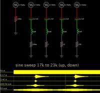
Screenshot showing the effects of various resistor values:


The scope traces show that a higher resistance produces a shallow curve.
A lower resistance produces a pronounced bulge at the center frequency.

However a very low resistance (.1 ohm) brings out a tendency to ring on and on. This is not an error of the simulator, proved by the fact that the ringing extends to the right of the center frequency whether the sweep is going up or down.
 
The performance of the energy storage inductor and capacitor usually isn't described in dB of attentuation, because the input to the filter is a square wave and the output is roughly a triangular wave (because the attenuation of the filter is frequency dependent). Usually we talk about things in terms of ripple voltage on the output, which is usually defined by the inductor ripple current multiplied by the capacitor ESR.

If you use a second filter after the first, then it's more reasonable to specify it in terms of dB, since the signal is more harmonically pure.
 
The performance of the energy storage inductor and capacitor usually isn't described in dB of attentuation
Nevertheless can it work for a rough estimation. Treating the switched voltage square wave magnitude as fundamental filter input frequency points at least in the right direction.

Referring to the original question, you get 1.5 decades frequency ratio, respectively about 650 Hz cut-off frequency. Exact filter calculations need to consider filter Q. I agree with mtwieg that capacitor ESR has been a dominant factor with electrolytic caps, but it rarely isn't with ceramic or foil caps.
 
Thank you all.

Infact I am working on very strict specifications, however I found a way to make my calculations, you might also be intersted in, therefore I am sharing it in bellow.

Decay Rate x Log (Fsw/Fc) = -dB
Decay rate for LC filter is = -40dB per decay
Fc => Corner Frequency
Fsw => Switching frequency
Subtituting all the values as mentioned, you can find the required Fc i.e;
Fc = 20kHz/(10^(-100/-40))
Fc = 63.24Hz
Since now we know the Corner frequency, we can find the required value for the capacitor i.e;
Fc = 1/((2xPixFc)^2 x L)

Actually I have allready calculated my inductor depending upon the maximum allowed current ripple, after calculating the inductor I calculated the corresponding Vripple using;

Vripple = Iripple x (Rl^2 + Xl^2)^0.5
Rl => Inductor resistance
Xl => Inductor reactance = 2xPixFswxL
If we ignore Rl the expression becomes;

Vripple = Iripple x 2xPixFswxL

Then I converted this Vripple to nominal ripple i.e. 10ppm.
Then converted to dB, then I came to know I need this dB attenuation at the switching frequency then I used the above method to calculate my corner frequency and then the capacitor size.

I would post additional Thread to have exchange of ideas regarding the damping circuit required to damp out the overshoot at the corner frequency of an LC low pass filter.

Thank you all. :)
 

Status
Not open for further replies.

Part and Inventory Search

Welcome to EDABoard.com

Sponsor

Back
Top