Continue to Site

Welcome to EDAboard.com

Welcome to our site! EDAboard.com is an international Electronics Discussion Forum focused on EDA software, circuits, schematics, books, theory, papers, asic, pld, 8051, DSP, Network, RF, Analog Design, PCB, Service Manuals... and a whole lot more! To participate you need to register. Registration is free. Click here to register now.

How to bias transistors in this circuit?

Status
Not open for further replies.

mr_monster

Member level 4
Joined
May 10, 2012
Messages
79
Helped
0
Reputation
0
Reaction score
0
Trophy points
1,286
Activity points
1,964
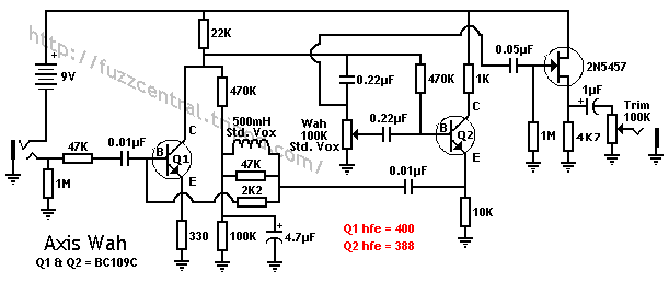
I have a guitar pedal like this with some transistors in it, I would like to use different transistors (modern ones) which might have different gains but bias transistors so that the device will operate the same way (and will sound the same way). The networks for the bias are a bit off-textbook so if anyone can help I would greatly appreciate it! This is only for Q1 and Q2 off course.


axiswahschematic.gif
 

I agree. As the transistors are simply high gain Silicon ones, adjustment shouldn't be necessary. It would be different if they were Germanium. The JFET is more of an issue because it is obsolete as far as I know, although you may still be able to find stock.

Keith.
 

I have found that small differences in gain are audible - for example, if I use a 380hFE and 400hFe transistor in Q1 I can hear a difference (gain measured at the same conditions).
What resistors to alter? The 330 Ohm from the emitter of Q1 and 1K from Q2 collector? Simply adjust for voltages with the input the of the device grounded?
 

Q2 is a unity gain buffer. Any reasonable gain transistor should perform about the same in that spot. No adjustments are necessary. But if you do want to adjust the gain then the emitter resistor (10k) would be the one to adjust. On the other hand Q1 is configured for a gain of 66 assuming the transistor has infinite gain. So to the extent that the actual transistor gain (hFe) is not infinite, that reduces the circuit gain to something below 66. Again it is the emitter resistor that adjusts the gain.
 

Q2 is a unity gain buffer. Any reasonable gain transistor should perform about the same in that spot. No adjustments are necessary. But if you do want to adjust the gain then the emitter resistor (10k) would be the one to adjust. On the other hand Q1 is configured for a gain of 66 assuming the transistor has infinite gain. So to the extent that the actual transistor gain (hFe) is not infinite, that reduces the circuit gain to something below 66. Again it is the emitter resistor that adjusts the gain.

How did you calc. gain for Q1?
 

The voltage gain of Q1 is set by 22K/330 ~ 66. The problem is that its a damped oscillatory circuit, so the "gain" is very dependent on the Q of the oscillatory circuit. BC109Cs had a massive spread on their Hfes coming from the manufacturers (250-470?), so unless the OENJ selected them for Hfe, the operation of the circuit should be set by passive component values. Are there any select on test resistors?
Frank
it would be helpful if you let us into the secret of what the gain changed from/to and the gizmos frequency response before and after.
Frank
 

This is a wah pedal (kind of band-pass filter with move-able band that turns to a LPF at lower freq.). The input is from an electric guitar and the output is to an amp.
 

Status
Not open for further replies.

Similar threads

Part and Inventory Search

Welcome to EDABoard.com

Sponsor

Back
Top