Continue to Site

Welcome to EDAboard.com

Welcome to our site! EDAboard.com is an international Electronics Discussion Forum focused on EDA software, circuits, schematics, books, theory, papers, asic, pld, 8051, DSP, Network, RF, Analog Design, PCB, Service Manuals... and a whole lot more! To participate you need to register. Registration is free. Click here to register now.

How to analyze the output voltage of this potesiometer schematic?

Status
Not open for further replies.

electronion

Newbie level 6
Joined
Nov 21, 2011
Messages
12
Helped
1
Reputation
2
Reaction score
0
Trophy points
1,281
Activity points
1,369
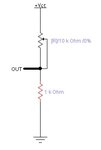
I am confuse how to analyze the output voltage of this schematic. do you know how much the out voltage if the potensiometer turn from 0% to 100%?. I've tried to simulate it in Electronic Workbench. and the result for 0% potensiometer turn is 5 Volt, for 50% is 3.32 Volt. How could it be 5 Volt for 0% and 3.32Volt for 50%?
Can you help me?
 

Attachments

  • Untitled.jpg
    Untitled.jpg
    7.9 KB · Views: 104

The value of potentiometer can vary from 0ohms to 10KOhms (assume it R1). The bottom is fixed 1Kohms (Assume it as R2). Assume the VCC=10V.
The R1 variable resistor will give you 10Kohms resistance for 0% position & 0ohms resistance for 100%.

The formula for output voltage( Vout) is Vout=VCC * [R2/(R1+R2)]

Condition 1 : (Assume R1=0%) 10Kohms. Here Vout= 10 * [1K/(1K+10K)] = 0.909V (Approximately 1V)

Condition 1 : (Assume R1=100%) 0ohms. Here Vout= 10 * [1K/(1K+0)] = 10V

So the 0-100% variation of pot will give you 0.9v-10v variation...
The voltage divider has 10:1 configuration....

Regards
Udhay
 

Don't get complicate. Apply ohm's law, Which states I = V/R. if ur Vcc = +5V. current through the string, I = 5/11KΩ => 0.4545mA .Take upper resistor as R1 and lower resistor as R2
1. If you moving the adjustable end of POT towards +Vcc(i.e., fully turned to one side), then it becomes,
voltage drop across R1, Vr1 = I * R1 => 0.4545mA * 10K => 4.54V. and drop across R2, Vr2 = 0.45V.
+5V------^^^^^^^^--------^^^^^--------gnd
---------10K---------------------1K-----------
------- R1------------------------ R2 -----------

2. If POT is exactly at center, then it becomes, take a rough sheet and draw, split the POT into two, as

+5V------^^^^----^^^^--------^^^^^--------gnd
------------5K--------5K-------------1K-----------
------- --- R1----------------------- R2 -----------
Vr1 = 0.4545mA * 5K => 2.2727V
As in your figure, it shows you are not measuring w.r.t ground. But i think while you simulating, all the voltages are w.r.t ground.

3. When POT is moved fully to another side, drop is zero .
+5V------^^^^^^^^--------^^^^^--------gnd
-------------------10K---------------1K-----------
--------------- R1 ----------------- R2 -----------

Best wishes :)
 

Status
Not open for further replies.

Part and Inventory Search

Welcome to EDABoard.com

Sponsor

Back
Top