Continue to Site

Welcome to EDAboard.com

Welcome to our site! EDAboard.com is an international Electronics Discussion Forum focused on EDA software, circuits, schematics, books, theory, papers, asic, pld, 8051, DSP, Network, RF, Analog Design, PCB, Service Manuals... and a whole lot more! To participate you need to register. Registration is free. Click here to register now.

how to analysis the S parameter when you simulate a transformer in momentum?

Status
Not open for further replies.

mustangyhz

Member level 5
Member level 5
Joined
Nov 18, 2008
Messages
87
Helped
0
Reputation
0
Reaction score
0
Trophy points
1,286
Visit site
Activity points
1,978
how to analyze the S parameter when you simulate a transformer in momentum?

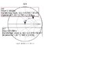
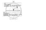
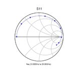
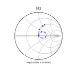
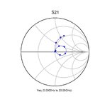
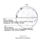
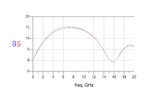
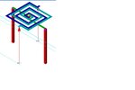
can you tell me the S parameter right or wrong? transformer.JPGs11.JPGs21.JPGs12.JPGs22.JPG
- - - Updated - - -

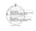
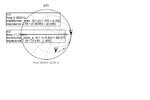
I think the impedance from S11 means Z11. Why the real part of Z11 is so large(2.000E9) when frequenz zero? Why the imaginary part of Z11 is negtive(-j1.626)? Does anybody know how to analyze the S parameter? can you tell me the layout of the transformer right or wrong? Does anybody have a project about transformer simulation in momentum?
thanks!!!
 

- - - Updated - - -

Something is completely wrong. Maybe missing ground reference.
can you tell me how to add the ground reference? can you check my project? I have attached the momentum project here, including the GDSfile, streammap file and the substrate file.
Help me!

- - - Updated - - -

I agree. The 3D view of the EM model looks ok, but there must be some gap (open circuit) in your metal path.
can you tell me how to add the ground reference? can you check my project? I have attached the momentum project here, including the GDSfile, streammap file and the substrate file.
Help me!
 

Attachments

  • transformer_prj.zip
    513.5 KB · Views: 57
  • gds-streammap-substrate.zip
    2.1 KB · Views: 124
Last edited:

can you check my project?

Why don't you do it yourself, to learn more about ADS and your model? This is your project.

The problem is the metal path from port to inductor to ground isn't complete. There must be a gap, or one of the metal properties is wrong. The curve that you see is the parasitic shunt capacitor to the substrate.
 
I have checked my project.
there is a gap!
thank FvM and volker@muehlhaus.

- - - Updated - - -

Why don't you do it yourself, to learn more about ADS and your model? This is your project.

The problem is the metal path from port to inductor to ground isn't complete. There must be a gap, or one of the metal properties is wrong. The curve that you see is the parasitic shunt capacitor to the substrate.

I think I have solved my problem:
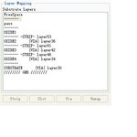
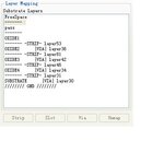
substrate file:
substrate file.JPG
modified substrate file
modified-substrate file.JPG
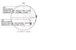
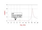
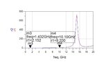
simulation results of the primary coil:
simulation results.JPG
can you tell me I am right or not? can you tell me some better way to solve this problem?
 
Last edited:

The resistance at low frequency is 0.038 * 50 Ohm = 1.9 Ohm now. This makes sense for the series resistance of your transformer coil.

- - - Updated - - -

Other equations that will be useful for transformer evaluation in the ADS data display:

Inductance of primary/secondary and coupling factor k:
Z = stoz(S)
Y = stoy(S)
omega = indep(S) * 2 * pi
L1 = imag(Z11) / omega
L2 = imag(Z22) / omega
k=sqrt(1-1/(Z11*Y11))
 
Status
Not open for further replies.

Part and Inventory Search

Welcome to EDABoard.com

Sponsor

Back
Top