Continue to Site

Welcome to EDAboard.com

Welcome to our site! EDAboard.com is an international Electronics Discussion Forum focused on EDA software, circuits, schematics, books, theory, papers, asic, pld, 8051, DSP, Network, RF, Analog Design, PCB, Service Manuals... and a whole lot more! To participate you need to register. Registration is free. Click here to register now.

How to amplifying small signal to high voltage

Status
Not open for further replies.

Max++

Junior Member level 3
Joined
May 24, 2006
Messages
29
Helped
0
Reputation
0
Reaction score
0
Trophy points
1,281
Location
Thailand
Activity points
1,495
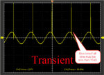
I'd like to generate the transient in power line system from D/A as image below.
Transient.jpg

There are 2 points that I want to know including.

1. How to amplifying small signal from D/A to very high voltage 220V?

2. How can I accomplish the rise/fall time of such level (10uSec at more than 500V)?

This signal is just voltage based supply to power analyzer. It is not drive to actual load anymore.
So, the current can be very small.

Please guide me to design the amplifier and appreciate if anyone can advise devices/or circuit that I should use in this design?

Thank in advance.
 

Perhaps a high voltage amp such as this would work.
They're not exactly cheap but I don't know that you will be able to generate such a high voltage, high frequency signal at a lower cost any other way.
For such a high voltage positive spike you can use unsymmetrical supply voltages such as +540V and -340V (900V absolute total maximum).

If you need more voltage you could possibly use two amps driven by opposite polarity signals with the outputs connected differentially to the load.
 
Last edited:

Hi,

Maybe an audio amplifier folowed by a transformer.

I once used a class D amplifier, a filter and a usual 230V/9V (reversed) transformer.

Klaus
 

I don't believe that a 50 Hz or wide band audio transformer will achieve the bandwidth to transmit the insinuated (not actually shown) "needle" pulses. You have to face transformer self resonance and respective waveform distortions.

I would go for high voltage analog amplifier. Another option would be to have separate channels for 50 Hz and high frequent surges.
 

Use a step-up series injection transformer and dump a capacitor into the primary. You can achieve rise times of 10's of nanoseconds without too much difficulty.
 

I would use an ignition coil driven from a 24Vac transformer and use a small polyurethane series Resistor + cap to discharge current limited arc from 24kV or 12Vac to 12kVac as a step-up transformer using a spark plug coupled to a choke isolated line voltage. rise time will be <1ns duration depends on RC time constant , current limited by V/R.

I would use old fashion big ignition coil with automotive resistance insulation wire, plug, ground and maybe a current limiting R on primary of coil if not limited b small XFMR.
The autotransformer has a BW of <50kHz but the discharge has a BW of > 1GHz.

Thus will simulate internal transformer Partial Discharge defects, but not lightning surge which is much lower impedance and bigger picoC of energy but same voltage.

Otherwise U can easily simulate it here with up to 30? harmonics. draw sine then mouse draw a spike...
https://www.falstad.com/fourier/

The Fourier results of a spike are easy to understand, using amplitude and phase option.
The harmonics are equal then decline rapidly to have a notch where the sine freq. fits in the pulse width, then it is recursive after this.

Tranformers rarely support more than 3decades like from 50Hz to 100MHz.
I found one car autotransformer can support an audio sig gen up to 25kHz with a turns ratio of 1k.
 
Last edited:

Use a step-up series injection transformer and dump a capacitor into the primary. You can achieve rise times of 10's of nanoseconds without too much difficulty.
What transformer can give nanosecond rise-times at the output with a 500V peak??
 

Status
Not open for further replies.

Part and Inventory Search

Welcome to EDABoard.com

Sponsor

Back
Top