Continue to Site

Welcome to EDAboard.com

Welcome to our site! EDAboard.com is an international Electronics Discussion Forum focused on EDA software, circuits, schematics, books, theory, papers, asic, pld, 8051, DSP, Network, RF, Analog Design, PCB, Service Manuals... and a whole lot more! To participate you need to register. Registration is free. Click here to register now.

How to amplify small swings in voltage?

Status
Not open for further replies.

jcarlson

Newbie level 4
Joined
Oct 31, 2016
Messages
7
Helped
0
Reputation
0
Reaction score
0
Trophy points
1
Activity points
59
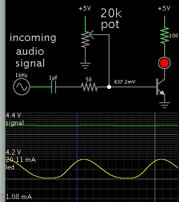
I've built a first, small AM radio and I'm just getting into electronics. I'd like to add a station strength indicator LED. The voltage exiting the amplifier stage varies by a small amount, 100 or 200 mV, based on signal. How can I amplify that swing such that the LED will vary output in a meaningful way? Just hooking it up with a proper resistor only gives the smallest of light flickers with signal changes.

Thanks for any direction you can give!
 

from which point you are extracting the signal strength voltage ?
after detector or any other? How did you measure it as 100/200mv?
 

Yes, after the detector and just after the amplifier (class B dual transistor). I used my volt meter to watch the change in voltage as I played with the tuning dial. I know it's not exact, but it was in the range of a couple hundred mV as the signal changed.
 

Hi,

What frequency? Audio or RF?

Klaus
 

Audio frequency. I know there must be a way to do this, I just don't know which components will get me in the right direction.
 

To be even more clear, I measured a swing of 4.2V to about 4.4V coming out of the amplifier stage, just before the audio signal hits the coupling capacitor to the speaker. This seems like the best place to tap in a signal strength LED because there's plenty of voltage. There is only ~1.3V - ~1.8V earlier in the signal pipeline. So my idea, was to take that .2V difference and magnify it so the swing is even wider, then power an LED which should vary in brightness with the signal strength.
 

I'd like to add a station strength indicator LED.

This is similar to broadcast carrier intensity. (Frequencies from 500-1700 kHz.) Is this what you want to know? It's different from audio volume.

- - - Updated - - -

swing of 4.2V to about 4.4V coming out of the amplifier stage, just before the audio signal hits the coupling capacitor to the speaker. This seems like the best place to tap in a signal strength LED because there's plenty of voltage. There is only ~1.3V - ~1.8V earlier in the signal pipeline. So my idea, was to take that .2V difference and magnify it so the swing is even wider, then power an LED which should vary in brightness with the signal strength.

A capacitor passes AC only to the transistor. Adjust bias carefully to make the led brightness proportional over the entire AC amplitude of incoming signal.

7178209700_1485201799.png


Notice the scope trace shows the incoming signal as 4.2-4.4V. The capacitor blocks the DC component. The transistor amplifies the AC component.

This circuit responds to each individual waveform. If you wish you can add a capacitor to create a peak detector, so that the led stays lit continuously through several waveforms.
 

Wow, this is perfect - thank you Brad! I understand how all the basic components work, it's just hard to know how to tie them together in interesting ways. I guess this will come from experience.

Thanks again!
 

Just a final message, I added the additional capacitor as well and it performs beautifully. Thanks for your help!
 

Status
Not open for further replies.

Part and Inventory Search

Welcome to EDABoard.com

Sponsor

Back
Top