Welcome to our site! EDAboard.com is an international Electronics Discussion Forum focused on EDA software, circuits, schematics, books, theory, papers, asic, pld, 8051, DSP, Network, RF, Analog Design, PCB, Service Manuals... and a whole lot more! To participate you need to register. Registration is free. Click here to register now.
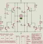
Please help me out to understand how this H-brigde is working?
i tried but i couldn't make any sense.
i found it through google.it is attached in the form of image..
thanks
Please help me out to understand how this H-brigde is working?
i tried but i couldn't make any sense.
i found it through google.it is attached in the form of image..
thanks
Dear,
its a simple circuit... when inputs A/B are LOW in that case Q5and Q6 will be in non conducting state..that is they will be OFF...and if they are off in that case they will not pull down the the base currents which is supplied by R1/R2 to Q1/Q4..making both Q1/Q4 to conduct/forward biased..and hence both of the motor terminals will be at supply VDC level...so Motor will be in STOP condition...
and if you just reverse the above condition at inputs A/B then you can see that maintaining both A/B input at HIGH level will turn Q1/Q4 OFF and also at the same time lower Q2/Q3 will conduct to ON...this all will bring motor terminals to ground level..again this will be a STOP condition for Motor...
from above explanations you can now understand how motor will be in forward/reverse condition when either of the A/B Inputs are HIGH...
Please try to go slowly and step by step in understanding any of electronic circuitry/schematic....then surely you will be able to get the logic involved...
Thanks to both of you For the Reply
but bro! i have still some confusions...
1) how did you predicted that when A/B input is HIGH then Q2 and Q3 will conduct?? i mean how are you so sure that Veb(For Q2 and Q3) is greater than 0.7V??
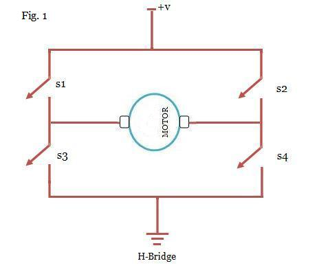
Click the switches marked A and B. Each sends power through the load in opposite directions.
What happens when you close both switches at the same time? At first we would think it is disastrous due to all transistors conducting. However this does not happen (as Aashitech points out in post #3).
If you install a load containing a coil, then the diodes are recommended as shown in your schematic (post #1).
I need one of these to control a 10 amp linear actuator (12 volt dc motor driven). I've tried various relay setups and the control signal pulses too much and burns up the contacts. This would be a 12 volt application. Would I just spec larger transistors for Q1 thru 4? (any ideas on which would work best would be appreciated). I assume this would all have to be on a heat sink as well for my application thanks
This site uses cookies to help personalise content, tailor your experience and to keep you logged in if you register.
By continuing to use this site, you are consenting to our use of cookies.