Continue to Site

Welcome to EDAboard.com

Welcome to our site! EDAboard.com is an international Electronics Discussion Forum focused on EDA software, circuits, schematics, books, theory, papers, asic, pld, 8051, DSP, Network, RF, Analog Design, PCB, Service Manuals... and a whole lot more! To participate you need to register. Registration is free. Click here to register now.

How measure AC voltage , maybe instrumentation amplifier

Status
Not open for further replies.

LokoGT

Newbie level 3
Newbie level 3
Joined
Feb 21, 2013
Messages
4
Helped
0
Reputation
0
Reaction score
0
Trophy points
1,281
Visit site
Activity points
1,314
Hello,
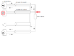
I need measure voltage in cicruits, see figure
Coaxial electrical properties can not be ignored.
I believe that it is necessary to use instrumentation amplifier, it is so?
What results can be obtained with instrumentation amplifier built from AD8620+AD8610 Gain=1 , see datasheet Figure 68 page 20
How to solve the problem as precisely as possible
V.png
 

I agree that a differential amplifier is required. You can refer to schematics of HP/Agilent LCR meters how they manage it.
 

You have true, but is need differential amplifier with relative high input resistance. I think subtractor circuit with input buffering and this is de facto instrumentation amplifier with gain=1.
Look to HP I also thought, 'I looked in the service documentation Agilent 4284A, unfortunately, this section does not appear in it.
I would be happy to find a service manual Agilent 4284A with complete circuits design.
Today we have the amplifiers as AD8620, yet I feel for the problem of accurate and Agilent 4284A began manufacturing 20 years ago.
As those guys from HP do? :roll:
 
Last edited:

Most instrumentation opamps are not suitable for frequencies as high as 1 MHz. To measure voltages at audio up to 1 MHz, instead of making and calibration wideband amplifiers, rather use a RF voltmeter calibrated over the frequency band. HP, Agilent, R&S and others offer such instruments.
To measure RF voltage, one needs a calibrated RF detector and a DC voltmeter. Here you can use an instrumentation opamp, as a D voltmeter.
 

Therefore, I am not talking about the instrumentation amplifier in one case, but the assembly from precision and fast amplifier. I thing AD8620+AD8610 is good choice.

Again I searched the HP documentation, and use the symbol for instrumentation amplifier.
f I have correctly identified the location of the image block components, it should be a U300 + U301 (small PCB)
U301 might be the RF amplifier, but equally it may be a PCB with classical instrumentation amplifier composed of the three amplifiers.
VCH.png
 

In the absence of a full schematic, the 4284 block diagram is still interesting in several regards:
- it clarifies, that the differential measurement is implemented with rather asymmetrical impedances. This doesn't particularly suggest regular instrumentation amplifier topology
- the low sense channel is actually implemented as a transimpedance amplifier, achieving a defined loop gain for the compensation controller

Detail requirements for the amplifiers have to be primarly calculated from application parameters. Phase and magnitude errors, noise, imput impedance can be translated into measurement uncertainty at the range margins.
 

Application parameters + - just match the 4284th Or I could use 4284 and the results would be OK. But it is a single-purpose device and make it so expensive for standing position is unthinkable.More less we solved most of the problems for up to two
1. Sensing amplifier for voltage measurement.
2. Switching outputs of the sensing amplifier amplifier stage. I wanted to use the analog switch, but do not have enough insulation between channels
Shame that HP removed from documentation schematic A3 board.
 

Status
Not open for further replies.

Similar threads

Part and Inventory Search

Welcome to EDABoard.com

Sponsor

Back
Top