umery2k75
Advanced Member level 1
This is taken from the book
INDUSTRIAL CONTROL ELECTRONICS
APPLICATION AND DESIGN
BY J.MICHAEL JACOB
Page #434
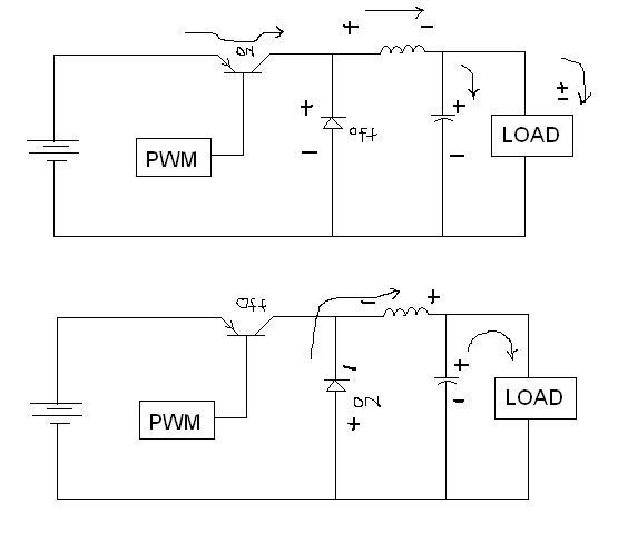
The author is explaining about forward converter
What is more or what is less?"The forward converter is a simple, popular switching configuration. When the transistor is driven on by the pulse-width modulator, it acts as a short,collector to emitter. The large positive voltage from the input filter is applied to the junction of the inductor and diode. The diode is reversed biased. Cur
rent begins to increase through the inductor , expanding the magnetic field in the inductor. (Remember, an inductor opposes a change of current through it.) Part of this increasing current goes to charge the output filter capacitor, increasing the output voltage. This part of opeartion cycle is shown in upper figure.
During the second half of the cycle, the PWM drives the transistor off. The almost instantaneous removal of current from the input filter forces the inductor to reverse the voltage polarity. It now acts as a generator, sourcing current as the magnetic field collaspes. This reversal in polariy places a negative on the cathode of the diode, turning it on. With the diode on, the left side of the inductor is clamped at a few tenths of a volt negative, placing this inductor(more or less) in parallel with the output capacitor and load.
I think J.Michael Jacob(Author) is saying so in terms of nodal voltage. Maybe the nodal voltage at the left side of the inductor reaches to 0V or even lower. So he might have said inductor becoming parallel with the output load.
I don't know, if this is correct to say about series/parallel arrangement. As far as I know component will become parallel only, when they are physically attach and not electrically attach because of similar volts at it's two ends.
Suppose if I found two SMD resistors in my computer, which are physically apart and also not connected together. One attach near to the processor and other attach near the VGA port, both of it's end have similar voltage. Can I still say resistor more or less becomes parallel?