Welcome to our site! EDAboard.com is an international Electronics Discussion Forum focused on EDA software, circuits, schematics, books, theory, papers, asic, pld, 8051, DSP, Network, RF, Analog Design, PCB, Service Manuals... and a whole lot more! To participate you need to register. Registration is free. Click here to register now.
Yes of course there is but the formula would be very complicated.
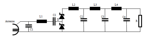
I would suggest the simplest method (which ignores phase shifts and residual capacitances/inductances but will give a reasonably accurate result) is to convert it to a resistor model and treat the antenna voltage, assuming that is the input, as DC. In reality it will be very frequency dependent.
So do this:
1. convert all the capacitors to equivalent resistances using the formula:
1/(2 * pi * f * C)
2. convert all the inductances to equivalent resistances using the formula:
2 * pi * f * L
3. for the diodes, subtract Vf from the voltage across them and calculate the power loss as Vf * I
Use the resistor as it is. The power loss in it is (V * V)/R
In the calculation, f is the frequency in Hz, C is in Farads, L is in Henries and R is in Ohms. When you have converted everything to it's equivalent resistance and calculated the total across the source, the power consumption is (source voltage * source voltage)/ total resistance.
As I said, the calculation is quite complex and will be inaccurate unless you also take into account the phase shifts and shape of the input waveform.
If you are refertng to a website related to simulation software you can search LTSPICE, microcap, orcad; this last two have evaluation version which require registration
This site uses cookies to help personalise content, tailor your experience and to keep you logged in if you register.
By continuing to use this site, you are consenting to our use of cookies.

")