Continue to Site

Welcome to EDAboard.com

Welcome to our site! EDAboard.com is an international Electronics Discussion Forum focused on EDA software, circuits, schematics, books, theory, papers, asic, pld, 8051, DSP, Network, RF, Analog Design, PCB, Service Manuals... and a whole lot more! To participate you need to register. Registration is free. Click here to register now.

How do I amplify the output voltage from function generator

Status
Not open for further replies.

buaaxd471

Newbie level 1
Newbie level 1
Joined
May 14, 2013
Messages
1
Helped
0
Reputation
0
Reaction score
0
Trophy points
1,281
Visit site
Activity points
1,292
Hi,

I'm right now using a function generator for a 10MHz to 40MHz 10Vpp (50ohm) output sine wave. But I want to increase the output voltage up to 40-50Vpp, and may also increase the output power at the same time. Does anyone have experience to increase the output voltage of function generator?

Thanks.
 

why not use an OP AMP . but i donot know if they reach the 40-50v . might need to use a transformerto increase voltage . and transistors (amplifier like a AB-BJT class amplifier) for increase current .

hope that helps
 

Just some basic estimating..

50v peak-to peak is 25V base to peak, and staying with 50 Ohms for now..
Then, for sine waves, the RMS voltage is 25/SQRT(2) = 17.67 Volts, and Power = V^2/50 = 6.25 Watts
For the other extreme, a square-wave of (say) 90% on, 10% off comes to 11.25 Watts.
Peak power is 25^2/50 = 12.5Watts.

To get more power at that voltage implies a lower output impedance output perhaps from a output follower buffer type final driver.

At 40 MHz, even for a sine-wave period 25nS, the transit through 50V from the positive peak to the negative is approximately half that, and for an arbitrary wave, might encounter slews in 5 or 6 nS. Slew rates then get into unlikely high numbers.

A 40 MHz 20Watt linear amplifier is not an unusual thing, though this requirement is for arbitrary waveform.
You would expect quality, low distortion output, with stable output impedance through 2 octaves. I could be wrong, but I think it probably more than a straighforward power op-amp could manage. Other folk in this forum may well come up with some suggestions for you.
 

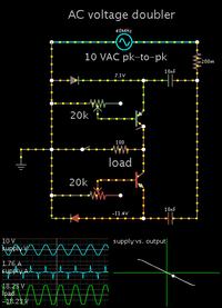
I have devised a schematic which simulates doubling AC amplitude (less diode drops).


It makes use of two Villard cells, at opposite polarity.

Your waveform generator will need to provide large current bursts.

It is essential to adjust the potentiometers until the lissajous figure (at right) indicates the load is receiving the same shape of waveform which is coming from the sinewave generator.

There ought to be a way to add another Villard stage, in order to triple the incoming AC.
 

I have devised a schematic which simulates doubling AC amplitude (less diode drops).

I am unfamiliar with Villard cells. Voltage doublers/multipliers using Cockroft-Walt style diodes and capacitor combinations I do know.

Does the Villard cell preserve the arbitrary waveform?
 

Does the Villard cell preserve the arbitrary waveform?

Yes, my usage of it does. Triangle, sawtooth, square waves. Pulsed DC does not remain pulsed DC, it is turned into a semblance of AC.

How it works:

During one half of the cycle, a capacitor charges immediately to the peak V of the supply. (That is, if there is no large resistance intervening.)

During the other half of the cycle, the transistor is biased by that half of the waveform. Hence it applies a matching waveform to the load.
 

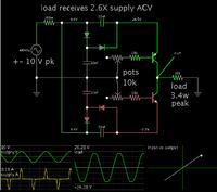
For curiosity sake, I added another Villard cell to each polarity. I managed to obtain 2.6X the AC supply.


This topology has to draw large current bursts, if your waveform generator can provide them.

The capacitor values appear to work at 40 MHz (in the simulation).
 

Status
Not open for further replies.

Part and Inventory Search

Welcome to EDABoard.com

Sponsor

Back
Top