Continue to Site

Welcome to EDAboard.com

Welcome to our site! EDAboard.com is an international Electronics Discussion Forum focused on EDA software, circuits, schematics, books, theory, papers, asic, pld, 8051, DSP, Network, RF, Analog Design, PCB, Service Manuals... and a whole lot more! To participate you need to register. Registration is free. Click here to register now.

How do digital oscilloscopes take a +-30V signal and scale the voltage

Status
Not open for further replies.

iceblu3710

Member level 3
Joined
Aug 10, 2009
Messages
61
Helped
1
Reputation
2
Reaction score
1
Trophy points
1,288
Activity points
1,955
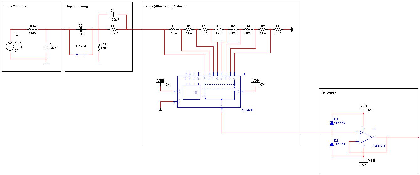
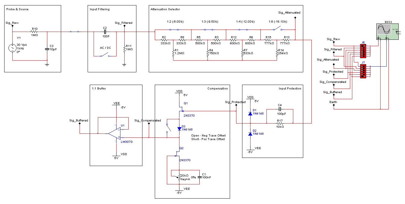
How do DSO's take a +-30V input signal and scale it so that the output swing is no more than the internal components, say 5V?

The only way I can think of is an opamp with programmable gain that when the input is <5V you have positive gain and >5V you need negative gain. Then put a couple zeners across the signal to protect things.

How do the pro's deal with this issue?
 

No no.. I want to know how they do it in hardware in a dso.
 

A resistive attenuator switched by relays and/or analogue switches. Also, you need a protection circuit for when you are on the wrong range and put 250V on the 20mV range.

Keith.
 
A "10X" probe is a 10:1 resistive attenuator (with comp /
peaking); from there the front end has step attenuation.
 

I will Google that when I get home from work thanks! I will post back my design ideas to.
 

So I found out a few things and have some options. First I found a ladder attenuator that is exactly what I need but I am having some troubble dealing with the switching. I then thought about using a string of resisters and mosfets to pull 'taps' off between the resistors effectively making a varyable voltage divider. Once again the switching is the issue as if I use n-channel fets I will need a bootstrap voltage to turn the upper ranged ones on. I also found out about analog mux ic's which is just what I want and you can get them with <100ohm on resistance (200x higher than a mosfet though) but in order to use them for the entire sweep I would need to provide them with the max +/- voltage I want to read. So now I would need two higher voltages I didn't plan on.

Here is my current idea, Haven't done any testing yet but I'm open to ideas still.


The attenuators would normally cover a 1:2:5 sequence. The resistor string idea doesn't work too well at high frequencies due to stray capacitances, but it depends on what frequency you are interested in. It is worth looking at relays - then you can withstand 250V. You will need protection for the buffer amplifier and some series resistance to limit the current in the protection diodes.

Keith.
 
Thanks for the help btw, this is the first time I have been dealing with attenuation on this level.

How about I use a Pi network with relays or mosfets shorting each Pi filter. With all filters bypassed I have 1:1 (+losses via relays/fets) then to enable each attenuation levels Pi filter all I need to do is open the relay (turn off the fet) and the signal will pass through filter. This way their is only ever one filter active and only 3 resistors as play. I have been using these equations and would need to fine tune things as my input stage and buffer have different impedances.

I wipped up a little Pi filter to test. 30V input at 1M Z, 5V output at 50k Z is 34.9Mohm to ground input, 677.5kohm to ground output and 1Mohm between. I have seen more complex filters with caps across the input/output resistors but I have no idea how to calculate these yet.

The goal is to get 1MHz as clean as possible as I am using a 12bit 15Msps ADC. Later on I want to try for ~30MHz but then things like PCB footprint come into play and I'm not ready for that yet.

Another question is when they say a 1Mohm input Z do they mean nominal with no probe (like my drawing) or with a probe attached? I'm thinking them mean with it attaches as if you where to put a 10:1 probe (10Mohm) with an internal 1Mohm to ground inside the equipment you now have less input Z than with a 1:1 probe which could be dangerous. Just want to make sure...
 

Yes, T attenuators are a good idea. Assuming you want a 1M ohm system then you would design for a 1M load. Add 1M to the buffer you use (a high input impedance buffer).

1MHz should not be too tricky, although with 1M ohm resistors it doesn't take much capacitance to start to have an impact. The extra capacitors are usually to compensate for the stray capacitance and keep a flat frequency response, a bit like the compensation capacitor in a x10 scope probe.

A 1M ohm input is 1M without a probe. The probe will have a 9M series resistor with compensation capacitor. It has no resistor to ground - it relies on the oscilloscope 1M ohm.

You first circuit won't work because you have a 1M resistor to ground but then 10k shorting it to ground. You need the resistance to be exactly 1M no matter which attenuator setting you have.

To protect the buffer you can put a resistor of say 10k or 100k in series and then add some low capacitance clamping diodes.

Keith.
 

I have switched to a switched T attenuation network and it is working nicely now. I am however having great difficulty at matching and even calculating the impedances for the front end before attenuation, buffer input Z, and then the ADC input Z. It all depends on frequency as well so I'm not even sure what to use as my numbers. I figured 50% my bandwidth goal sounded good so I am trying to set all stages at 1M ohm impedance at 500kHz.

I am going to find a better probe/source equivalent model and add some probe calibration circuity as well to make things a bit more tuner friendly on PCB.

Thanks for the links Alex theirs a few different designs out there but not much explanation on why they chose those exact values. (Bitscopes is pretty good though)
 

Well I did some more work and the downside to using a spice package is that you need to know the electronics and the crazy spice lingo to make it all work right...


It work and now it doesn't.

Oh well its the next step of the design, added some compensation. Note that the diode between to FET's would be a diode or 0R resistor in real life depending on if the signal needs a positive or negative offset.

Each piece of the puzzle works seperately but when I put them together the attenuator stops working correctly and theirs clipping errors as a result (from the protection diodes and the buffer) I'm going to put money on each stage is not properly impedance balanced and thats why they do not play well together but I am having issues as the spice package keeps trowing timing faults.

Well when I measure the front end before input protection I get 180k ohm Z and its pretty linear across 0-1MHz by about +/-2 ohms. Its not the 1M ohm I was hoping for but the linearity is nice to see.
 

Your model of a probe is not correct. A x1 probe has nothing in it other than maybe 100pF of cable capacitance. A x10 probe has a 9M resistor with parallel trim capacitor.

PM sent.

Keith
 

In addition, you should also provide compensation capacitors for high resistance (100k - Mohm range) attenuators. They can't work without it, even at moderate signal frequencies.

I noticed, that some DYJ oscilloscope circuits suggest solid state relays like PVT312 for input switching. Inspecting the capacitance versus voltage characteristic of these devices raises doubts, if the author has ever operated his circuit above audio frequencies.
 

Status
Not open for further replies.

Part and Inventory Search

Welcome to EDABoard.com

Sponsor

Back
Top