Continue to Site

Welcome to EDAboard.com

Welcome to our site! EDAboard.com is an international Electronics Discussion Forum focused on EDA software, circuits, schematics, books, theory, papers, asic, pld, 8051, DSP, Network, RF, Analog Design, PCB, Service Manuals... and a whole lot more! To participate you need to register. Registration is free. Click here to register now.

How Can I remove spikes from square wave???

Status
Not open for further replies.

jay496

Newbie level 6
Joined
Nov 27, 2013
Messages
11
Helped
0
Reputation
0
Reaction score
0
Trophy points
1
Activity points
77
I am working on VCO I simply used the ring oscillator method.... and giving the control voltage(Vct)

for some control voltages (say vct=0.15) O/P doest have the Full swing :sad:

So I thought of using buffers and have noted the square O/P :-|

But the O/P have spikes :-( how can I remove them

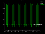
Normal O/p say Vct=0.25
normal_output.png

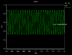
Buffer O/P
Buffer_output.png


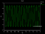
Vct=.15
normal_output_Vct_0.15.png

Thanks,
Jay
 

Does your testbench include the realistic load at the output?
 

No realistic Load.. I am taking o/p directly... I am using Synopsys( Hspice)
 

Those are likely the result of normal circuit stray inductance and capacitance. Are the spikes a problem or do you just not like them?
 

So I thought of using buffers and have noted the square O/P :-|
But the O/P have spikes :-( how can I remove them

You need show the circuit diagram in order to allow us provide an accurate hint.


+++
 

Those are likely the result of normal circuit stray inductance and capacitance. Are the spikes a problem or do you just not like them?

I am asking as it is not looking good for me....

- - - Updated - - -

You need show the circuit diagram in order to allow us provide an accurate hint.


+++

Actually I am writing the netlist in hspice so no diagram.....

The Figure would be VCO followed by 6 buffers(Inverters)....
 

Any suggestions please........?????????
 

The suggestion was gave on topic #5:
You need provide the circuit schematic to allow us take some analysis of the possible reason.


+++
 

Hi Jay,

These spikes are related to coupling capacitance between the input and the output of the inverter (Cgd of both transistors). Also, they depend on the capacitance you are driving. Spikes are large, for instance, if you are driving small capacitance with large inverter. If you want to remove them you simply need to decrease sizes of your driving transistors for the same output capacitor or increase the output capacitor. However, you will lose switching speed if you do so (slope), it is a trade-off (as everything in IC design).
 

jay496, did you hear already about "median filtering"?
This rechnique was developped in particular for such cases you have shown in your first post.
 

Your oscilloscope is a fake (software) one. Maybe it is causing the spikes.
 

Status
Not open for further replies.

Part and Inventory Search

Welcome to EDABoard.com

Sponsor

Back
Top