Continue to Site

Welcome to EDAboard.com

Welcome to our site! EDAboard.com is an international Electronics Discussion Forum focused on EDA software, circuits, schematics, books, theory, papers, asic, pld, 8051, DSP, Network, RF, Analog Design, PCB, Service Manuals... and a whole lot more! To participate you need to register. Registration is free. Click here to register now.

How can I reduce levels of a pulse?

Status
Not open for further replies.

hannover90

Member level 4
Member level 4
Joined
Dec 8, 2009
Messages
70
Helped
0
Reputation
0
Reaction score
0
Trophy points
1,286
Location
Germany
Visit site
Activity points
1,784
Hello,

I want to reduce the level of a pulse from 2.5V/5.0V to 0V/2.5V.

The common levelshifters rise the levels of the pulse (from 2.5V/5V to 5V/7.5V).

Does anyone has an idea, how can I reduce the level of a pulse?

Many thanks in advance.
 

Hi,
Maybe a pulse tranformer could to the job.
Alternatively, you can use a comparator, supplied with 2.5V and with 5V tolerant inputs, put the threshold at (5-2.5)/2, it should work.
Or, you may use a serial capacitor to get rid of the 2.5 DC voltage, and use a comparator with 2.5V supply.

Hope this helps.
 
Use a series decoupling capacitor and then a resistor to GND (CR differentiation element).
 
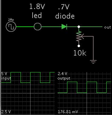
The right combination of led/ zener/ diodes, will drop 2.5V from your signal.

You may have to accept some amplitude reduction.
The potentiometer may or may not be needed.

2616061100_1403794791.png
 
Use a series decoupling capacitor and then a resistor to GND (CR differentiation element).
For that technique to work you will likely need to add a Schottky diode clamp (diode across resistor, anode to ground) to avoid level shifting as determined by the duty-cycle of the pulse. This will cause the bottom of the pulse to be about 0.5V below ground, which can't be readily avoided.
 
Use a series decoupling capacitor and then a resistor to GND (CR differentiation element).

For that technique to work you will likely need to add a Schottky diode clamp (diode across resistor, anode to ground) to avoid level shifting as determined by the duty-cycle of the pulse. This will cause the bottom of the pulse to be about 0.5V below ground, which can't be readily avoided.

You're totally right, crutschow, I forgot this. But even adding the Schottky diode clamp doesn't seem to help a lot: View attachment CR-lvl-shft.pdf

But I don't really trust this simulation result. Why wouldn't it clamp?
 

..............................
But I don't really trust this simulation result. Why wouldn't it clamp?
Dunno. My simulation (below) works fine. It would appear your diode model is not working, since obviously you can't have that much forward voltage across a normal diode without many amps of current.

Clamp.gif
 

It would appear your diode model is not working
You're right again, crutschow: The BAS40 Schottky diode is too "weak", i.e. has too much series resistance. The stronger 1N5817 actually clamps correctly (even if my 1N5817 model seems inferior to yours) ;-) : Clamp_2.gif
 

Status
Not open for further replies.

Part and Inventory Search

Welcome to EDABoard.com

Sponsor

Back
Top