Continue to Site

Welcome to EDAboard.com

Welcome to our site! EDAboard.com is an international Electronics Discussion Forum focused on EDA software, circuits, schematics, books, theory, papers, asic, pld, 8051, DSP, Network, RF, Analog Design, PCB, Service Manuals... and a whole lot more! To participate you need to register. Registration is free. Click here to register now.

How can I drive 5" seven segment x6 with MCU ?

Status
Not open for further replies.
Do you mean the size of a numeral is 5 inches? This suggests it will be seen from a distance. I guess it needs to be bright?

The microcontroller is not likely to put out sufficient power to drive it directly.

In that case you must drive each segment from a transistor which is biased by the MCU output pins. You must make signal polarity cooperate with your common anode display. You'll need to choose NPN or PNP (whichever responds properly to signal polarity). You may need to invert signal polarity.

Seven segments will require 7 transistors.

Are you multiplexing six digits? Then you need to turn on each numeral separately from the other five. You'll need another 6 transistors to do this.
 

yes 5 inches 7 segment, yup to be bright, I've put PNP transistor on the common anode side, but I need 13.6V to make it bright, I didn't put NPN transistor on 'a','b','c'.....'g' side, it's bright already, can I drive PNP base with 0V from MCU directly ?

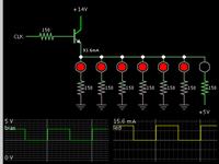
Please see the schematic, is it ok if I replace 5V directly to 13.6V and drive the transistor from MCU ? 0V from MCU = active..
Thanks
common anode circuit 5v.jpg
 

Is it ok if I replace 5V directly to 13.6V and drive the transistor from MCU ? 0V from MCU = active.
No, this doesn't work. You need a level translator, an additional NPN transistor can do the job. Either in CE configuration (inverting) or in CB configuration (non-inverting).
 

As it turns out, a single NPN will do the job (theoretically). This is because your supply is sufficient voltage.


I applied 5V to the last led, to show it will turn off when the MCU sends 5V.

Ordinarily we would want to place a PNP where your schematic shows. But it would need 13.6V at the bias in order to shut off the PNP. You would need an additional NPN to be a level translator (as FvM points out).
 

Thanks for the opinion, can you show me the circuit please ?
Would it be like this ?
big seven segment circuit.gif
What value should I use for the resistor ? 1K each ?

Thanks
 

Basically good.

There must be series current limiting resistors in each segment line (e.g. collector of TR10).

The base resistors should be chosen to drive the transistors into saturation independent of current gain type variation. For power transistors with relative low B, Ic/Ib = 10..20 is usually a safe value. Small signal transistors with B > 200, Ic/Ib = 50 can be sufficient. I don't know the projected segment current, but making all resistors 1 k will probably work.
 

Status
Not open for further replies.

Similar threads

Part and Inventory Search

Welcome to EDABoard.com

Sponsor

Back
Top