Continue to Site

Welcome to EDAboard.com

Welcome to our site! EDAboard.com is an international Electronics Discussion Forum focused on EDA software, circuits, schematics, books, theory, papers, asic, pld, 8051, DSP, Network, RF, Analog Design, PCB, Service Manuals... and a whole lot more! To participate you need to register. Registration is free. Click here to register now.

How can I connect two pc power supples in parallel?

zxpa

Junior Member level 2
Joined
Mar 27, 2024
Messages
20
Helped
0
Reputation
0
Reaction score
0
Trophy points
1
Activity points
94
I have two old regulary working pc power supplies.
Is it possible to connect this two power supplies +12V outputs and Masses in parallel
to have +12 and more current from both ones?

Blueberry PSB400
1.jpg


JNC
MODEL: LC-B300ATX
1.jpg


I want to connect them in such way:
+12V output of first one and +12V output of secound one
Mass output of first one and Mass output of secound one

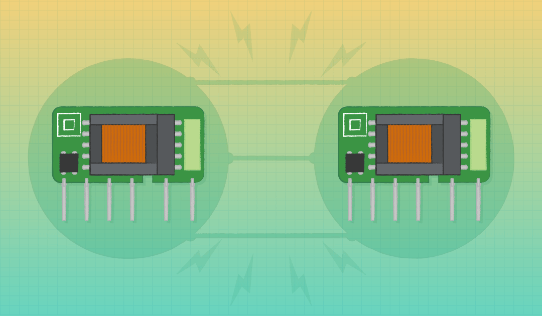
I considered this article:
{597} Connect 2 Power Supplies in Parallel to Get More Current
 
The problem is current sharing capability. If your supply does not have that then only way you can
connect in parallel is thru two diodes :

1712941216121.png
that

Keep in mind this does not guarantee current sharing but aids it. Diodes of course
drop some voltage, so you have to compute if a heat sink is needed for each diode.
And of course the closer the two supplies matched in output V the better the sharing
is. Also if diodes are matched.


Regards, Dana.
 
Connecting two PC power supplies in parallel to increase the current output is possible, but it requires some caution and modification. Here's how you could potentially do it:
  1. Isolation: Make sure both power supplies are isolated from each other. This means they should have independent grounds and no common connections apart from the ones you're intending to create.
  2. Prepare the power supplies: Open up both power supplies and locate the +12V and ground wires. You will need to disconnect these wires from the PC board to use them externally. Be cautious when opening power supplies, as they contain capacitors that can hold a dangerous charge even when unplugged.
  3. Connect the outputs: Connect the +12V output of the first power supply to the +12V output of the second power supply. Similarly, connect the ground (mass) output of the first power supply to the ground output of the second power supply.
  4. Load balancing: It's essential to balance the load between the two power supplies to ensure they share the current evenly. You can do this by connecting your load (whatever you're powering) across both sets of outputs.
  5. Safety precautions: Ensure proper insulation and secure connections to prevent short circuits or accidental disconnections. Use appropriate gauge wires and connectors rated for the current you expect to draw.
  6. Testing: Before connecting any sensitive or expensive equipment, test the setup with a load similar to what you intend to power to ensure stability and proper functioning. Monitor the temperature of the power supplies during operation to ensure they're not overheating.
  7. Considerations: Keep in mind that modifying power supplies in this way may void their warranties and could potentially be hazardous if not done correctly. If you're not comfortable working with electronics or unsure about any step, it's best to seek assistance from someone with experience or consult a professional. Additionally, be aware of any legal or safety regulations regarding modifying electrical equipment in your area.
 
In the ARRL handbook I saw advice we should balance current through two diodes or two transistors, by installing a low-ohm resistance inline with one or both devices. Otherwise the devices could be mismatched. We can regard your power supplies the same way. One is rated for fewer Amperes. Even with voltage regulation it might not always be stable. You don't want its volt output to exceed the other supply because this asks the weaker to supply overmuch current. The aim is to ensure its volt output never exceeds volts coming from the stronger power supply. A resistance of 1/80 ohm develops 1/4 V when 20A goes through it. Maybe 1/4 volt is cautious enough. Careful monitoring is called for by your instruments.

It can be contributed by a few inches of wire. Notice it wastes several Watts of power and heat is produced.
 
Hi,

I see paralleled diodes. You know it doesn´t work satisfactory.
What´s your intention to do so?

Klaus
 
No it is not paralleled it is my mistake here is the correct diagram again:
1.png


I made mistake by using this picture:
1.png

And I made mistake using this picture:
1.png
 
Last edited:
Hi,

did you read the MBRxxx datasheet about forward current specification?

Klaus

Added:

My opinion about your idea:
It´s difficult to parallel two identical power supplies. But paralleling two different power supplies with different initial voltage differetn load behaviour, different power ratings ... is rather difficult and needs an active circuit for useful power distribution.
Passive solutions suffer from drifts, or are rather lossy (heat).

We could help you more if we knew more about the application, especially the load.

Klaus
 
Last edited:
I have just this type of diodes at present in my boxes I think I could use them but I cannot use full current power from +12V outs of supplies. I will need to buy stronger diodes about 20 A.

10.0 AMPS. Schottky Barrier Rectifiers
Maximum Recurrent Peak Reverse Voltage (VRRM): 200V
Maximum RMS Voltage (VRMS): 140 V
Maximum DC Blocking Voltage (VDC): 200V
Maximum Average Forward Rectified Current I(AV): 10A
See Fig. 1
Peak Repetitive Forward Current (Square Wave,
20KHz) at Tc=135oC IFRM
20.0 A
Peak Forward Surge Current, 8.3 ms Single Half
Sine-wave Superimposed on Rated Load (JEDEC
method ) IFSM: 150 A
Maximum Average Forward Rectified Current I(AV): 10A
I will describe the application I need them for it.
 
The MBR10200 nominal ESR resistance is between 0.1 Ohm @ 1A 25C and 0.3 Ohms @ 7A 125'C meaning the voltage drop can vary instantly from 0.1V and 2.1V . Now sharing with two couple diodes splits this half.
1/80 ohm or 0.0125 Ohm won't do any harm but wont do any good.
If your video card normally gets 2% regulation error filtered in BW by GBW of regulator and above that the bulk Caps. adding diodes eliminates all this filtering benefit plus adds load regulation errors on the 12V line up to 1.05V/12V*100%= 8 % error. I am not sure how sensitive your video card is to supply noise but that will be a lot if the load is dynamic. Adding low ESR bulk caps will help that. BW=0.5/C*1.05ohm . Choose 10kHz BW and estimate C= 50uF low ESR = 0.04 ohms.

To improve this it may be possible to not use the 5V shared as this is the primary feedback for load regulation on all PC PSU's. The other outputs are regulated by mutual coupling of up to 99.9%. This means the 5V mismatch will not create instabilities fighting over current sharing affecting the voltage output on all outputs. Although the series ESR of the diodes reduces this effect by degrading the load regulation from 1 or 2 % to 8%.

This is certainly a poor man's solution and we don't know your expectations or assumptions. I would not share the 5V or 3.3V supplies., the 12V lines in your video card ought to handle the loss using it's " high-tech"(?) SMPS and LDO step down converters.
 
KlausST
We could help you more if we knew more about the application, especially the load.

I want to drive a Piezo Horn connected at four BJT NPN and PNP transistors bridge circuit.

3-0068361_piezo-horna-khs-106.jpeg

Code:
ZV-KHS106
Characteristics:
300/150 W , 2-20 KHz , 90 dB

Specification
Dymensions: 95 mm
Music power (4 Ohm) : 300W
Music power (8 Ohm) : 150W
Frequency range: 2000 - 20000 Hz
Sensitivity: 90 dB
Max. voltage : 35 V ~

I have circuit for driving it but I can drive it only at max +12V power supply.
I want to drive it at full power of 150W or 300W.

By my calculation for Piezo Horn
P=150W, V=35V, I=4.28A,
P=300W, V=35V, I=8.57A,

I have the following power supplies I mentioned at the begin of this thread:
Blueberry PSB400
+12V, 12.0A, 144W

JNC MODEL: LC-B300ATX
+12V, 15.0A, 180W

I can use the secound JNC power supply for Piezo Horn driving at 150 Watts

But I want to make general purpose circuit from this two power supplies to drive my Piezo horn
at full 300 Watts

KlausST
is rather difficult and needs an active circuit for useful power distribution.

Please if you or somebody could give me an example of an active circuit
to distribute power from these both power supplies, from +12V outputs?

I read this article
and I found the sentence:
Power supplies A and B need to have the same Vout; Iout maximum can be different
 
Last edited:
A bridge amplifier, either linear or class D, needs at least 50 VDC supply to output 35 V sine signal. Even if you drive the speaker with square wave, you still need 35 VDC + some margin for amplifier voltage loss.

The other point is that a piezo horn doesn't actually consume 150 or even 300 W because it doesn't have 8 or 4 ohm impedance. These are purely fictive numbers.
 
I read somewhere that piezo alarm horn was 16 ohms at some single frequency. Is this your plan?
If so, then drive it with a square wave using a step up regulator after you verify the Z(f) of the piezo.

Something doesn’t smell right with specs showing 8/4 ohms and 4 terminals. Piezo’s are subject to resonance where they measure max output pressure waves. But this crappy cheap horn cannot dissipate 300W of heat! That would need an oil cooler. Piezo’s also do not have voice coils rather they are a planar dielectric with a crystal-like structure with wire bonds.

You’ve been scammed.

Otherwise on the PSU plan

--- Updated ---

The optimal current sharing design depends on each supply’s tolerance to backdriving without damage. Do you have a CC/CV Lab supply to find out?

Otherwise I have design for a lower than 0.7V current sensing voltage drop current limiter so you can have the one with higher no-load voltage limit safely while the secondary supply takes over set to the voltage with bigger supply voltage at full load. Therefore you need to find these parameters before the design can be done.
 
Last edited:
Hi,

as otheres already mentioned: there´s something wrong.
it´s not
* 2x 12V power supplies --> combined (diodes) --> piezo
there needs to be something inbetween
* 2x power supplies --> combined --> [unknown] --> piezo

The [unknown] usually is some kind of audio amplifier. In your case it is in best case a H-bridge driving +/-12V square wave to the piezos.
Now +/-12V square wave is surely less than the given 35V you need to generate 150W/300W.
this 35V usually are given in RMS sine, this means +/-50Vp or 100Vpp.
And - as already mentioned - this is "idealistic", but not realistic.
Driving just 12V into a ohmic load that is rated for 35V/150W (8 ohms) .. just results in a tiny 17.5W.

Audio specifications often are more "marketing values" than true values following physics.
A 150W specification for a piezo in best case is mean you can build a speaker box equipped with different speakers for different ranges of frequency.
The 150W then means the total power of music. But music is not a single tone of full power. Music is dynamic in amplitude. A 150W music may be just 15W of average power over a minute or so. And the power that hits a piezo (usually used for high frequency of audio) then may be less than 1W in average.

If you really push 150W through this piezo (By raisng the input voltage a lot), don´t be surprised if it gets dsetroyed within a couple of seconds.

I recommend to start with simple tests, as single 12V power supply ... and doing current measurements ... starting with low power level then increasign it.
You (sadly) need to expect a piezo to get destroyed during this test.

Klaus
 
Current-mode-controlled supplies sometimes offer current
sharing. We designed our POL DC-DC chips to do "one
wire current sharing" (plus a little fiddling with local set-
components & pin strapping).

If your supplies are current mode controlled and you feel
up to the task of figuring it out and rewiring the "slave"
to use current-controlling error voltage from one, to drive
the "back end" of the other, and can do it clean, you might
get proper operation.

1713401929966.png

1713401978175.png

1713402127033.png
 
Current-mode-controlled supplies sometimes offer current
sharing. We designed our POL DC-DC chips to do "one
wire current sharing" (plus a little fiddling with local set-
components & pin strapping).

If your supplies are current mode controlled and you feel
up to the task of figuring it out and rewiring the "slave"
to use current-controlling error voltage from one, to drive
the "back end" of the other, and can do it clean, you might
get proper operation.

View attachment 190215
View attachment 190216
View attachment 190217
Brilliant for someone who has a real problem and knows what a Piezo looks like which is not this small woofer with a tiny magnet that is good for 30 W before it melts.
It's a scam. I wonder why there are no real specs on the web (LOL)
 
The optimal current sharing design depends on each supply’s tolerance to backdriving without damage. Do you have a CC/CV Lab supply to find out?
No I don't have I am a beginner but I have made some simple electronic projects already.
--- Updated ---

A bridge amplifier, either linear or class D, needs at least 50 VDC supply to output 35 V sine signal. Even if you drive the speaker with square wave, you still need 35 VDC + some margin for amplifier voltage loss.

The other point is that a piezo horn doesn't actually consume 150 or even 300 W because it doesn't have 8 or 4 ohm impedance. These are purely fictive numbers.
I already assembled NE555 buck boost converter so I can generate about 60 Volts and 5 Amperes from +12 Volts power supply. It should be aboout 300 Watts of power.
 
Hi,

I already assembled NE555 buck boost converter so I can generate about 60 Volts and 5 Amperes from +12 Volts power supply. It should be aboout 300 Watts of power.
Hard to believe.
With NE555?
Why buck?
If so, it should be an easy thing for you to use two of these "NE555 buck boost converters". One for each 12V power supply and just combine the regulation loop for power sharing.

Klaus
 

LaTeX Commands Quick-Menu:

Part and Inventory Search

Welcome to EDABoard.com

Sponsor

Back
Top