tengyy
Member level 1

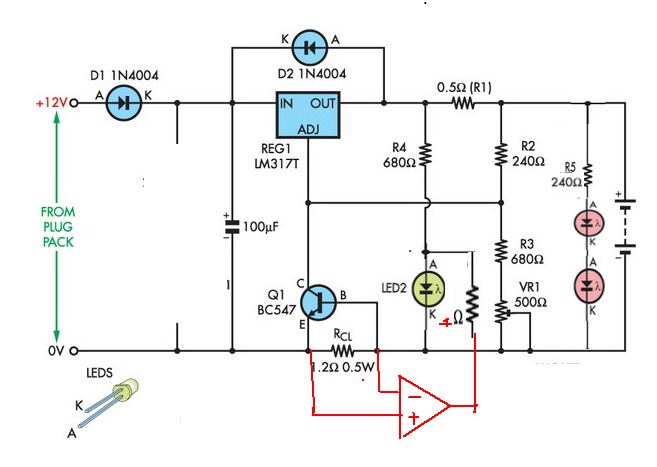
one NiMH 1.2V cannot light up the LED1, i think that is due to insufficient current. but with two 1.2VNimh battery can light up.
So, how can i adjust the resistance value in order to light up the LED1, or how to increase current in the LED 1 way when i plug in one NImh battery?
- - - Updated - - -
k... solve it... jst adjust the value of R1.... but still under investigate wat value suitable for it...