Continue to Site

Welcome to EDAboard.com

Welcome to our site! EDAboard.com is an international Electronics Discussion Forum focused on EDA software, circuits, schematics, books, theory, papers, asic, pld, 8051, DSP, Network, RF, Analog Design, PCB, Service Manuals... and a whole lot more! To participate you need to register. Registration is free. Click here to register now.

How a Charge Cuttoff works

Status
Not open for further replies.

smhn72@gmail.com

Member level 3
Joined
Oct 5, 2012
Messages
60
Helped
0
Reputation
0
Reaction score
0
Trophy points
1,286
Activity points
1,702
Salam to all

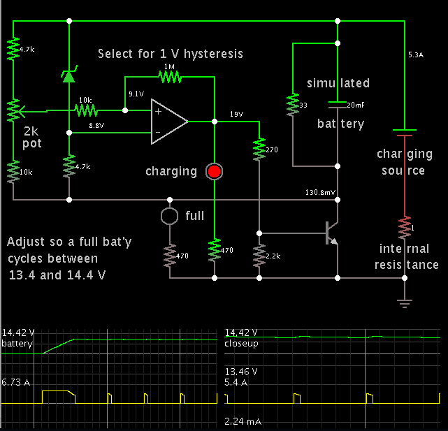
i want to know how a charge controller works and how this give cutoff to a battery when the battery becomes full???????
 

First think of it simply, like this:

There's an active switch between the charge source and the battery. This can be, for example, a MOSFET.

It's gate is controlled by a microcontroller or control circuit, which detects battery level. If battery level is higher than a predetermined level, indicating that the battery is fully charged, the microcontroller sends a zero to the gate to turn the switch off. The switch was in between charging source and battery. So, turning the switch of means turning the charging off. When battery is not fully charged, as determined by microcontroller or control circuit, a 'high' is sent to the switch gate to turn it on and thus commence or continue charging.

Hope this helps.
Tahmid.
 
Hi
To control charge you must know the capacity (mAH) of the battery. To cut off the battery (against Over discharge)you are constantly checking voltage using a microcontroller (ADC) or an analog comparator. This turn off the MOSFET at the output of battery terminals.
To know how much charge the battery has you should use Gas Guaging IC. This tells you how much charge is accumulated over a period of time. The low cost microcontroller will communicate with this IC and then you decides for Switching off Relay of the charger. This depends on Battery Chemistry, temperature and lot of other parameters. Normally Gas Guaging is done via sensing voltage across a low value shunt resistor that is usually in milli ohms. For explanation read the following document for gas guage https://www.ti.com/lit/ds/slus077a/slus077a.pdf and https://www.ti.com/lit/an/slva102a/slva102a.pdf.
 
Last edited:

Dear TAHMID Sir can we use metal oxide semiconductor field-effect transistor (MOSFET) to make solar charge controller. If it is possible then what will be the connections of the Input 19v DC of Solar Pannel with MOSFET?????????
ans sir what are the limits of MOSFET that it can manage watts maximumly mean if i connect 100 watt pannel will this work or not??????

thanks for help
 

Of course you can use MOSFET. Most charge controllers use MOSFETs.

The connections will depend on the topology and control scheme.

The limits of the MOSFET will depend on the ratings of the MOSFET itself. Multiple MOSFETs can be connected in parallel to give greater current handling capacity as well as lower overall combined RDS(on). You must select MOSFETs with adequate VDS rating. So keep that in mind.

Take a look at these:

http://www.solorb.com/elect/solarcirc/scc3/
http://www.solorb.com/elect/solarcirc/spc3/
http://www.solorb.com/elect/solarcirc/scc2-orig/index.html

Hope this helps.
Tahmid.
 
Dear THAMID Sir Thanks you very much for nice help
Sir tel me form where can i get the PCB of scc3???????
I could not understand one thing in The litrature sent by you plz explain a little bit by an example
that is following

"It is important to match the solar panel's current rating to the battery's amp-hour rating (C). A typical maximum battery charging current is C/20, so a 100 amp hour battery should have a solar panel rating of no greater than 5 amps."

Plz explain it a little bit because i m confused
 

What that particular statement means is:

The battery is charged at a maximum rate of 1/20 th its capacity. This should be the panel rating. A 100Ah battery is charged at a maximum of (100/20)A = 5A and this is the stated panel rating.

It might be due to circuit design.

Batteries are also commonly charged at C/10. In fact this is more common than C/20.

Hope this helps.
Tahmid.
 
Thanks Dear Thamid Sir

Sir i asked about PCB of SCC3
if i collect the electronic parts then these are useless for me till when there is no PCB availbale
so now what is for PCB solution?????
 

This is a simple charge controller which I constructed for my PV panels and battery bank. It switches on a mosfet to provide bulk charging.


When the battery reaches 14.4V, it shuts off the mosfet. The battery has some time to settle and cool.

When it drops to 13.4V (after several minutes), charging resumes.

The battery charges as quickly as possible, then cycles up and down in the space of 1V the rest of the afternoon.

It is a clumsy substitute for a taper charge. Nevertheless my design avoids overcharging, while minimizing any obstacle to current flow.
 

Typically discharge and charging time for starter type of lead acid is C/10, and for Deep cycle type of lead acid is C/20.


Additional to this topic, its nice to make charger device with showing delivered Ah to the battery, and showing internal resistance value, this can help in diagnostics and make picture of battery shape and status.
 

Thanks Dear Thamid Sir

Sir i asked about PCB of SCC3
if i collect the electronic parts then these are useless for me till when there is no PCB availbale
so now what is for PCB solution?????

You can purchase the kit. Quite expensive though.
You can design your own PCB as you are given the schematic. There are many PCB design software available, many of which are free.
 

Dear BradtheRad Plz tel me how many amperes can it controll maximum????????????????????????????????
 

Dear i asked about the circuit diagram that you sent me
this circuit holds how many amperes
 

Dear i asked about the circuit diagram that you sent me
this circuit holds how many amperes

The hardware version I constructed carried several amperes. It uses a mosfet rather than a transistor.

I did not test the controller with my entire solar panel output. Once I got it working I put it aside for a later day.

The Falstad simulator is not particular about safe component ratings. You must determine your needs and select components accordingly.

For example, the mosfet must be rated for the maximum current, and maximum volt levels, it will be exposed to.

Likewise for the op amp.
 

Dear i asked about the circuit diagram that you sent me
this circuit holds how many amperes

You can scale it for your required current by selecting appropriate components. The most critical component that dictates current handling capacity is the MOSFET/transistor. Select a MOSFET/transistor rated at higher than the maximum current and voltage it will be exposed to, as BradtheRad has pointed out. Make sure that, for safety, you maintain some margin between actual values and MOSFET/transistor capacity.

Hope this helps.
Tahmid.
 
Tahmid,
For a solar charger panel voltage must be boosted to a certain level and then the battery is charged am i right?
 

In simple circuits, the panel is chosen such that the output voltage is quite a bit higher than the battery voltage (under good amounts of sunlight). So, no voltage boosting is necessary. It may be necessary to scale down the voltage using a buck converter if the panel voltage is too high.

If panel voltage is normally lower than or around the battery voltage, then it will be necessary to boost up the voltage. Just remember that a battery needs a voltage higher than its rating to be charged. For example, a 12V battery is charged with voltages in excess of 13V.

Hope this helps.
Tahmid.
 

A panel rated 12V has a sufficient number of cells to charge a 12V battery in sunlight.

Each cell only puts out a couple of volts. Manufacturers had to join enough cells together so they will overcome battery voltage. They found that a good volt level (unloaded) is 20 to 25 V.

When you hook up a battery, the volt level automatically drops to battery voltage. No harm is done because in this usage the panel is a current source rather than a voltage source.
 

Status
Not open for further replies.

Part and Inventory Search

Welcome to EDABoard.com

Sponsor

Back
Top