mtwieg
Advanced Member level 6

- Joined
- Jan 20, 2011
- Messages
- 3,907
- Helped
- 1,311
- Reputation
- 2,628
- Reaction score
- 1,435
- Trophy points
- 1,393
- Activity points
- 30,018
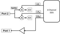
Hello all, previously I finished a project in which I basically made a simple VNA designed for analyzing pulsed RF amplifiers. I used a AD9959 quad channel DDS to generate the RF and quadrature LOs directly (my frequency range is 10-150MHz). I used homodyne conversion, so therefore the RF and LOs were at the same frequency. For this project, I was only interested in measuring forward transmission coefficients (S21), and didn't really care about reverse transmission (S12) or reflections (S11/S22). This figure shows my basic homodyne architecture:

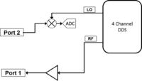
However I wanted to take things up another step and use a heterodyne downconversion to eliminate offset errors due to baseband detection. Also I thought it might reduce the required hardware by eliminating some mixers and ADC channels. I imagined it like this second figure:

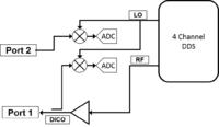
However I think that it's not so clear when I think of how the phase measurement works. One advantage with the homodyne design is that since the RF and LOs are at the same frequency and are always phase locked (due to being generated by one DDS), I could measure the phase of S21 just by looking at the I/Q ports at the receiver (port 2). However, with heterodyne downconversion, the LO and RF are at different frequencies so obviously there is no phase lock. In this situation, is it correct to say that in order to get an absolute measurement of phase, I have to also sample the power out of port 1, and sample it after downconverting it using the same LO as used on port 2? This means I still need two mixers, two ADC channels, a splitter for the LO, and a DICO on port 1, like shown below:

So after all is said in done, is there actually going to be a significant advantage to moving from baseband to heterodyne? I'll get rid of baseband offset errors, but then won't things like matching between IF filters become a problem? And aperture delay variation on the ADC channels?

However I wanted to take things up another step and use a heterodyne downconversion to eliminate offset errors due to baseband detection. Also I thought it might reduce the required hardware by eliminating some mixers and ADC channels. I imagined it like this second figure:

However I think that it's not so clear when I think of how the phase measurement works. One advantage with the homodyne design is that since the RF and LOs are at the same frequency and are always phase locked (due to being generated by one DDS), I could measure the phase of S21 just by looking at the I/Q ports at the receiver (port 2). However, with heterodyne downconversion, the LO and RF are at different frequencies so obviously there is no phase lock. In this situation, is it correct to say that in order to get an absolute measurement of phase, I have to also sample the power out of port 1, and sample it after downconverting it using the same LO as used on port 2? This means I still need two mixers, two ADC channels, a splitter for the LO, and a DICO on port 1, like shown below:

So after all is said in done, is there actually going to be a significant advantage to moving from baseband to heterodyne? I'll get rid of baseband offset errors, but then won't things like matching between IF filters become a problem? And aperture delay variation on the ADC channels?