Vermes
Advanced Member level 4

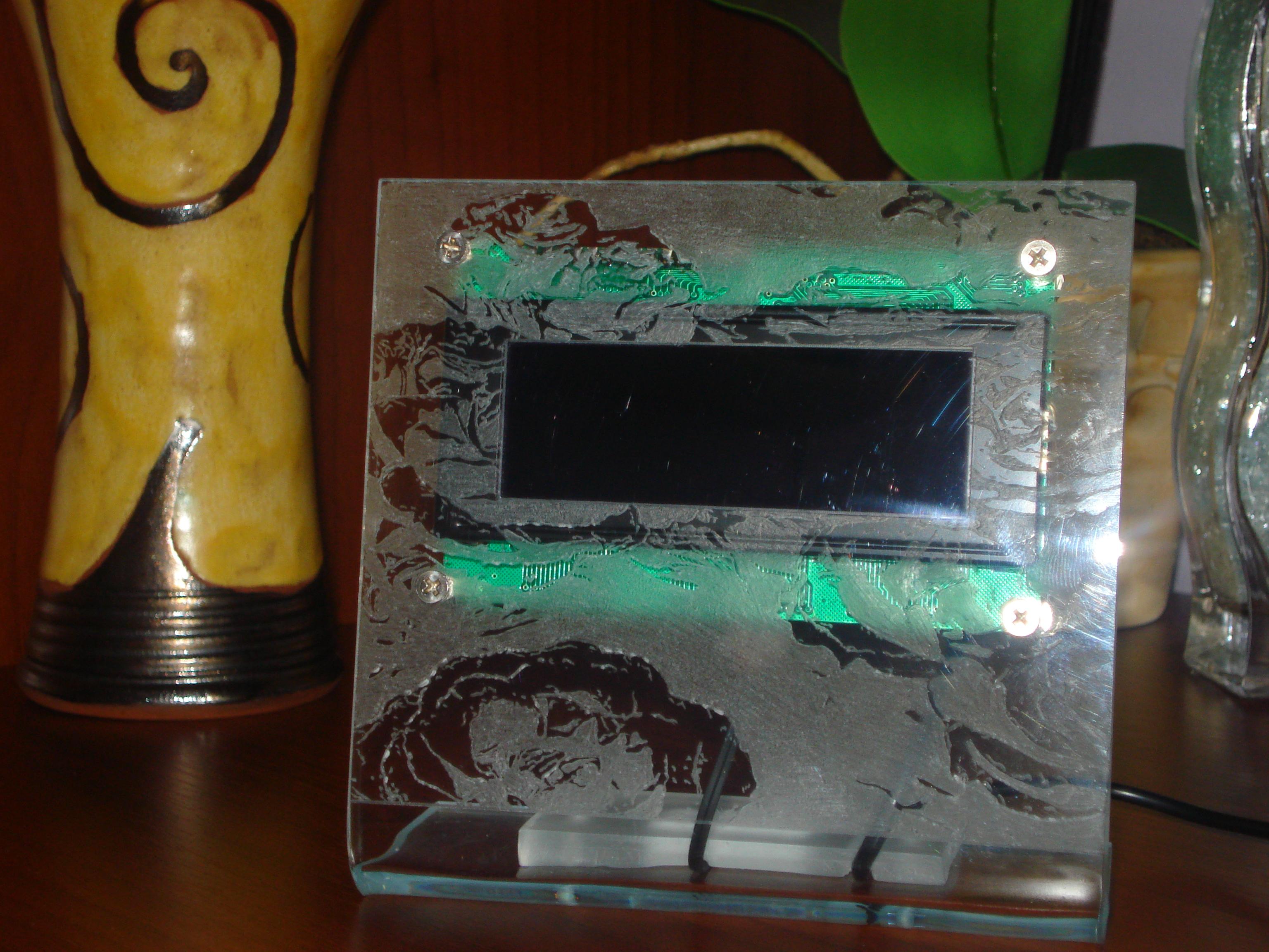
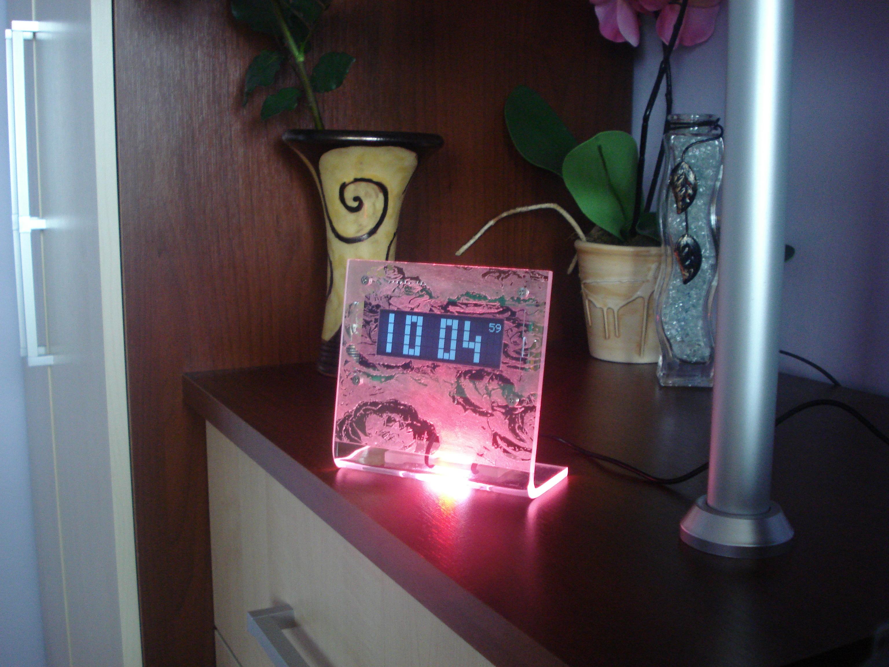
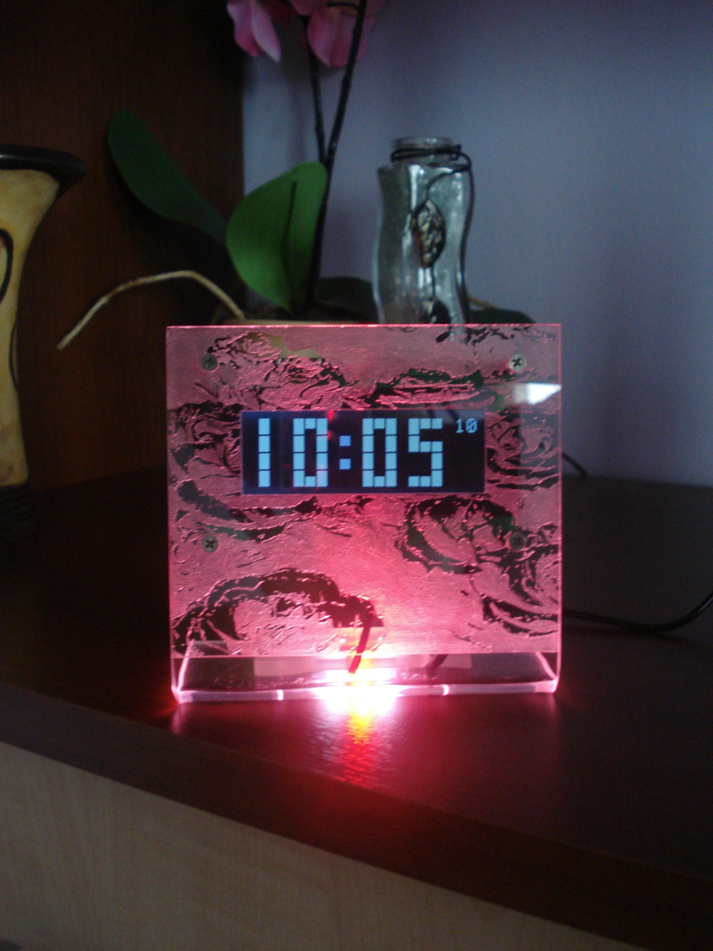
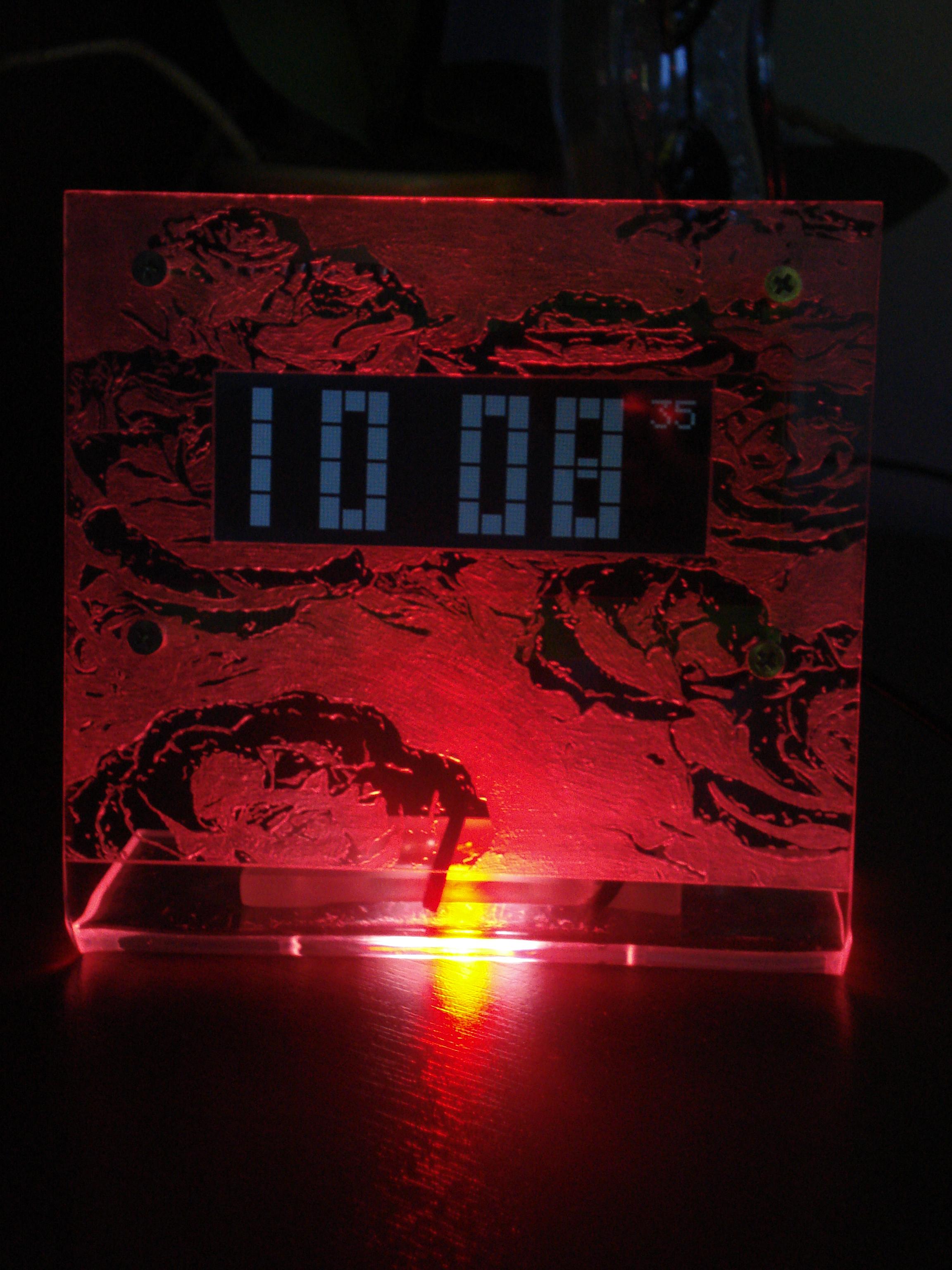
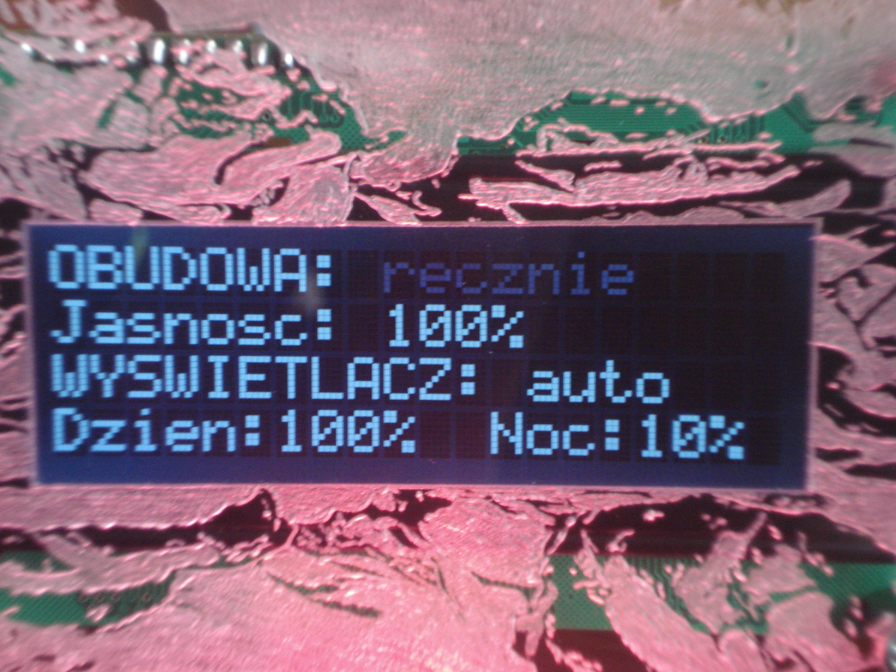
The aim of this device was to combine the clock with alarm (for each seven days of a week) and date. Backlight of the display and housing adapts to ambient brightness, so it is not too strong at night and clearly visible during the day.
Features:
- alphanumeric 4x20 displays compatible with HD44780
- remote control
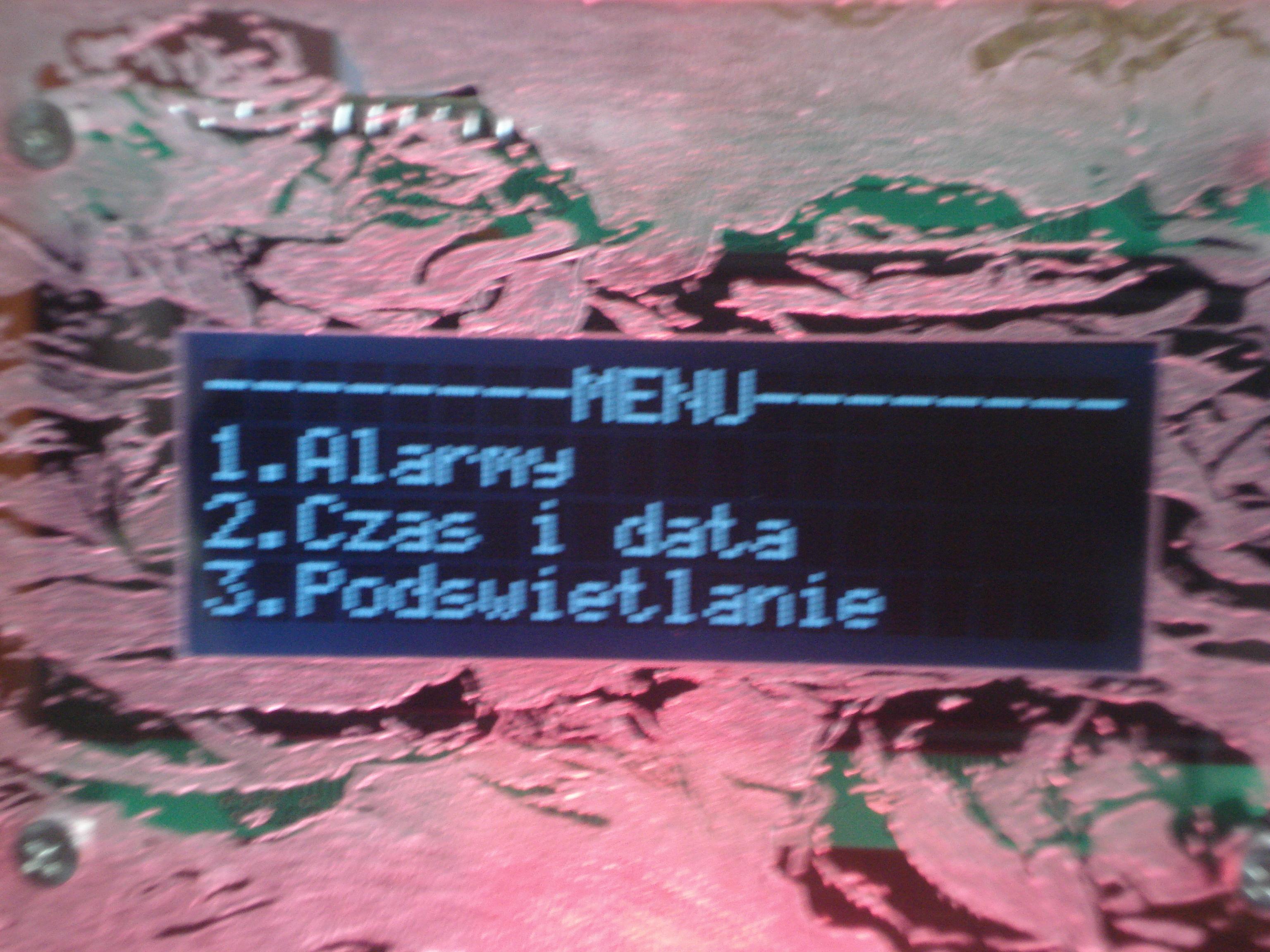
- alarm clock
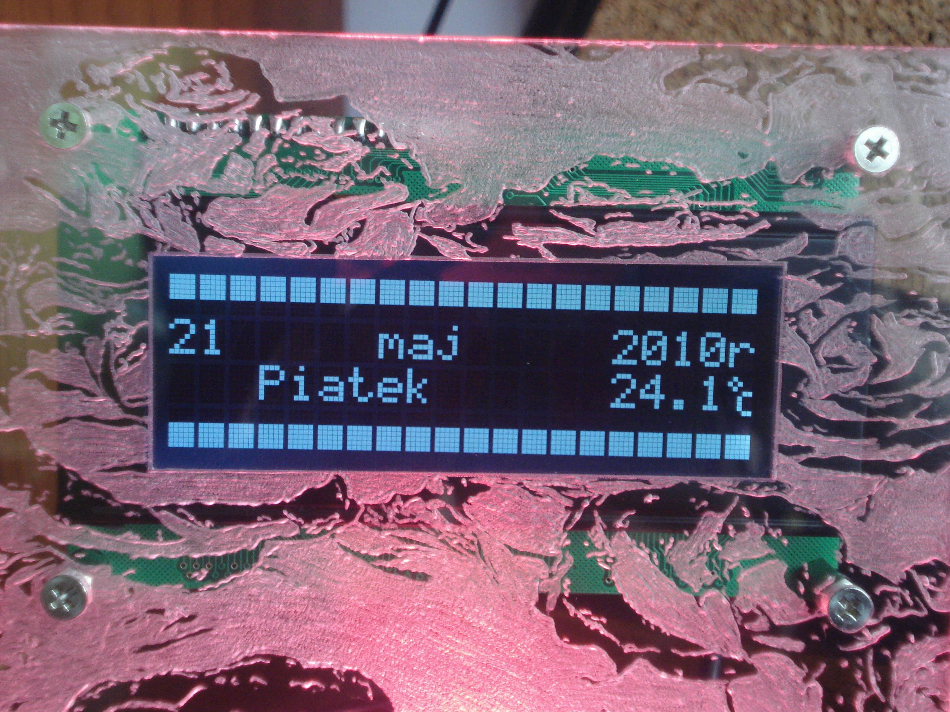
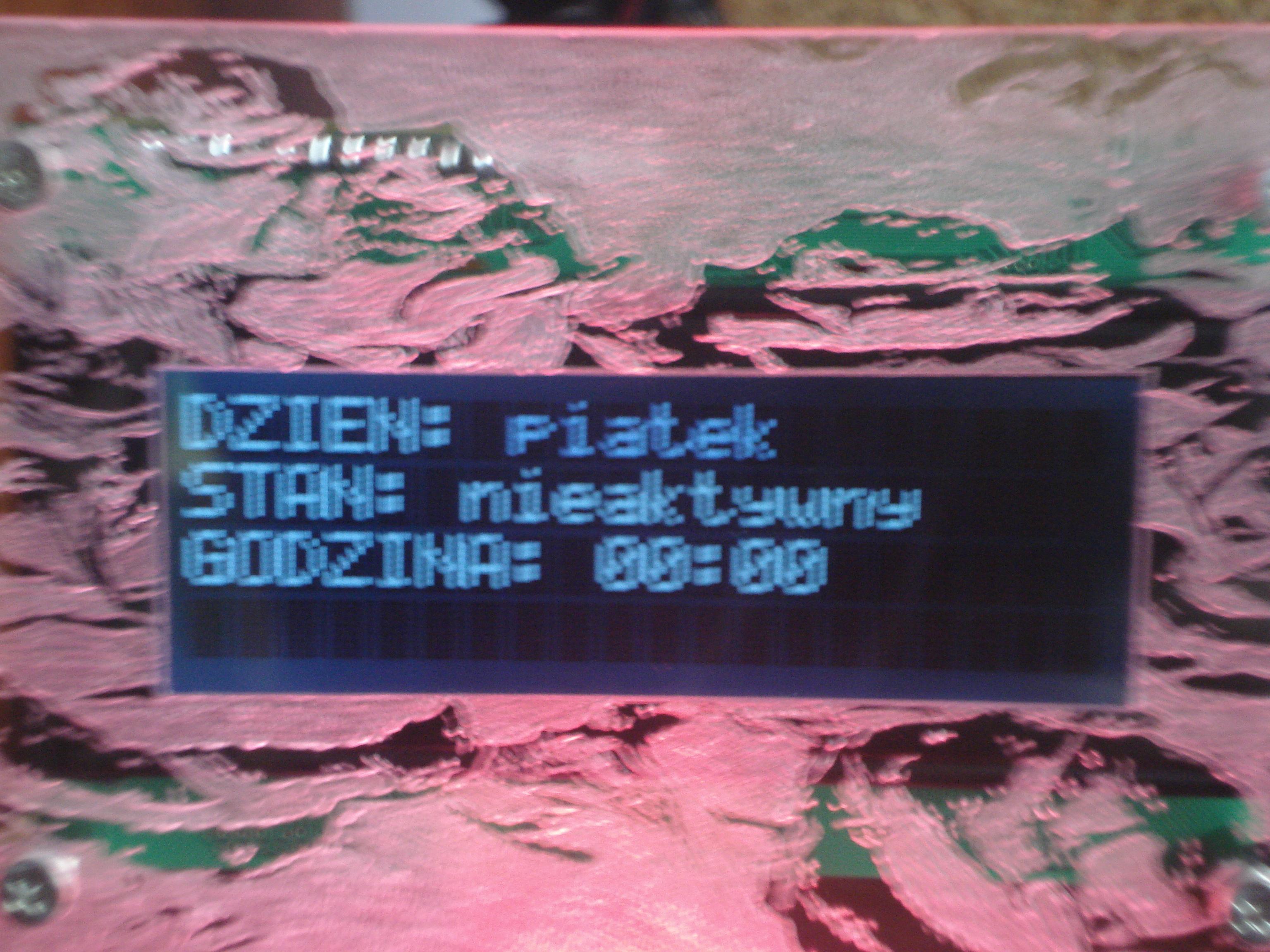
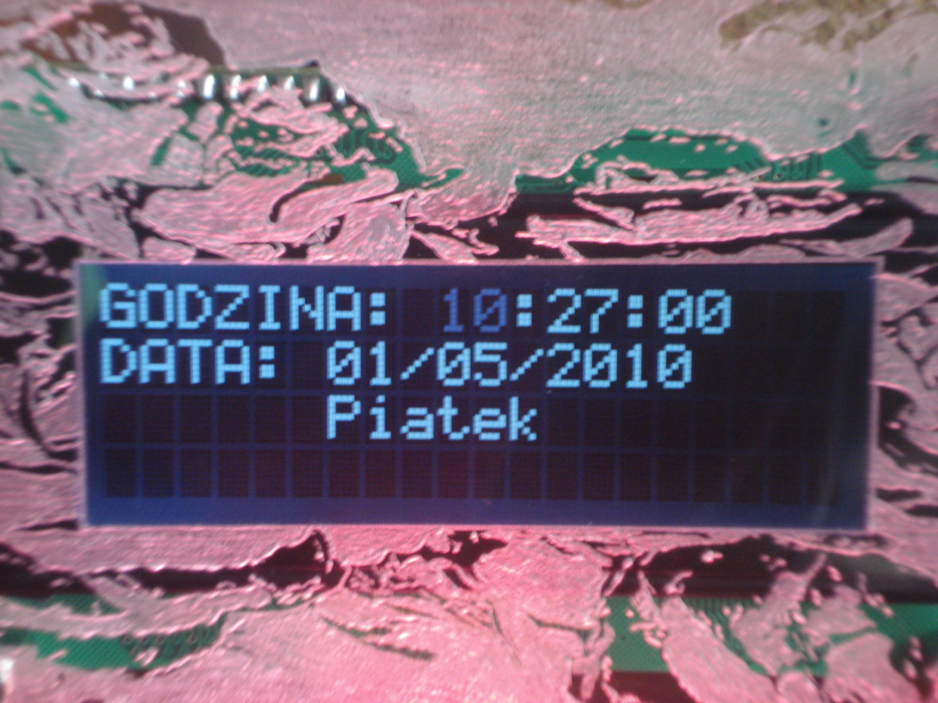
- displaying time and date
Prototype was made on a contact board while making program:
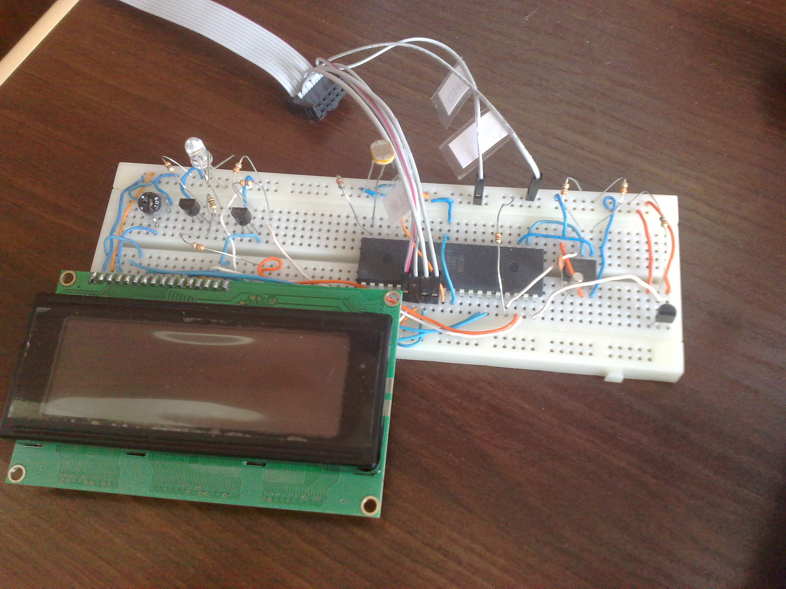
Program was written in Bascom. Characters showing the time are large enough to be visible when you get up and your eyes are still asleep.
Fonts:

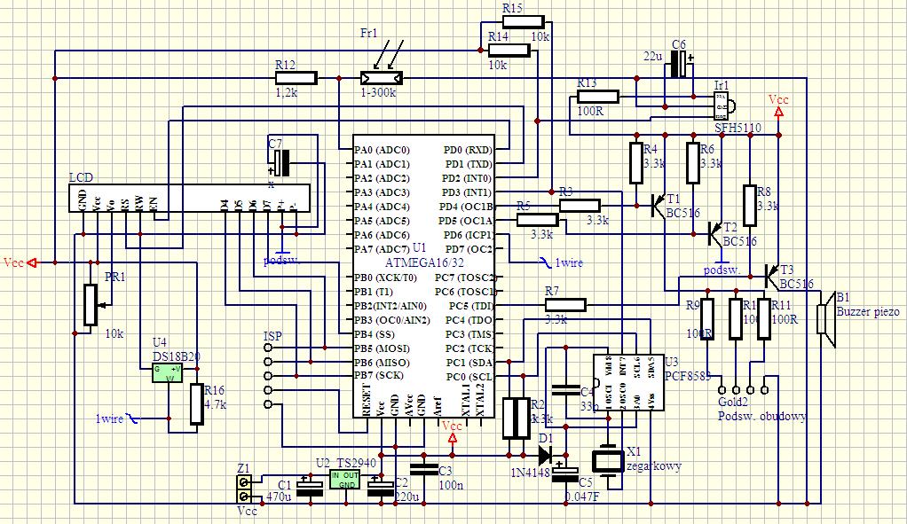
Popular RTC PCF8583 countdowns time. The program supports days of the week and leap years. Calendar can countdown any number of years (up to 65535). Two PWMs on timer1 control the buffers on Darlingtons BC516, which in turn supply diodes of the display and housing. Checking the ambient brightness is performed by the divider of photoresistor, resistor and A/C converter of the microcontroller. To avoid fluctuations and unpleasant flicker, the read is saved without conversion and counting to word variable, and then divided by 10. That means that the integers got are in the range of 0 to 10. Such an accuracy is sufficient for this purpose. RC5 signals receive is carried out on a typical IR receiver 36kHz – SFH5110.
Scheme:
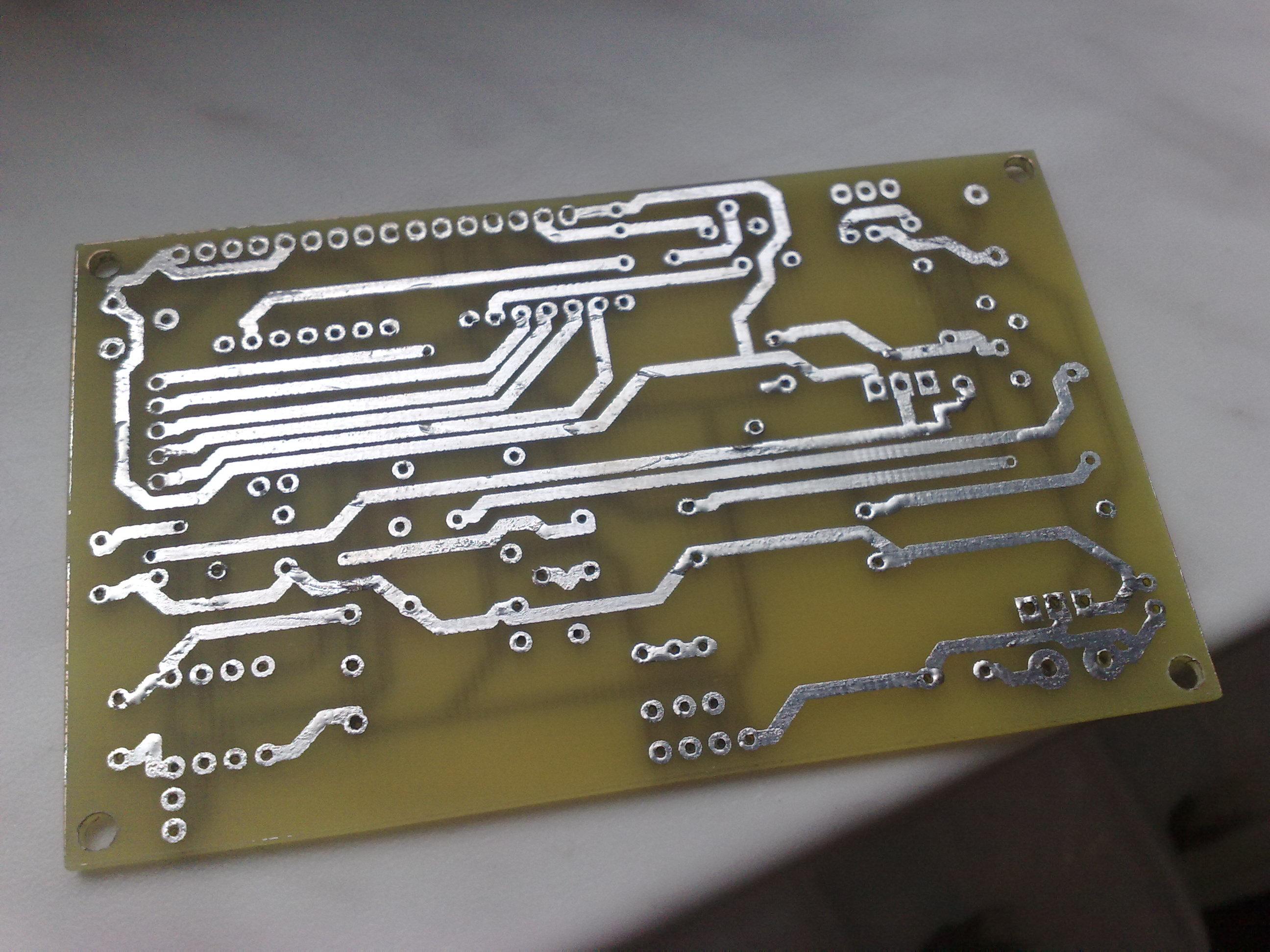
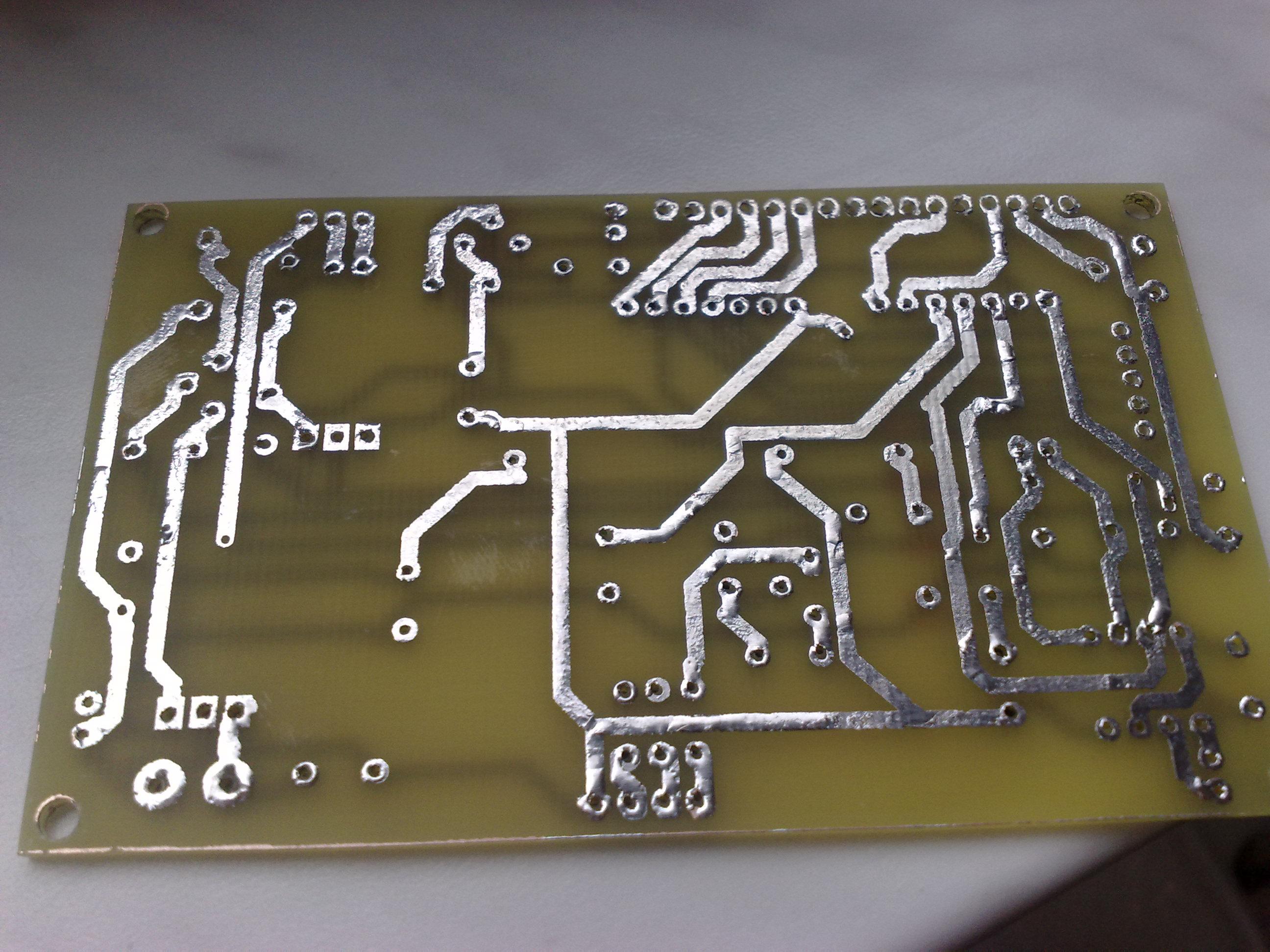
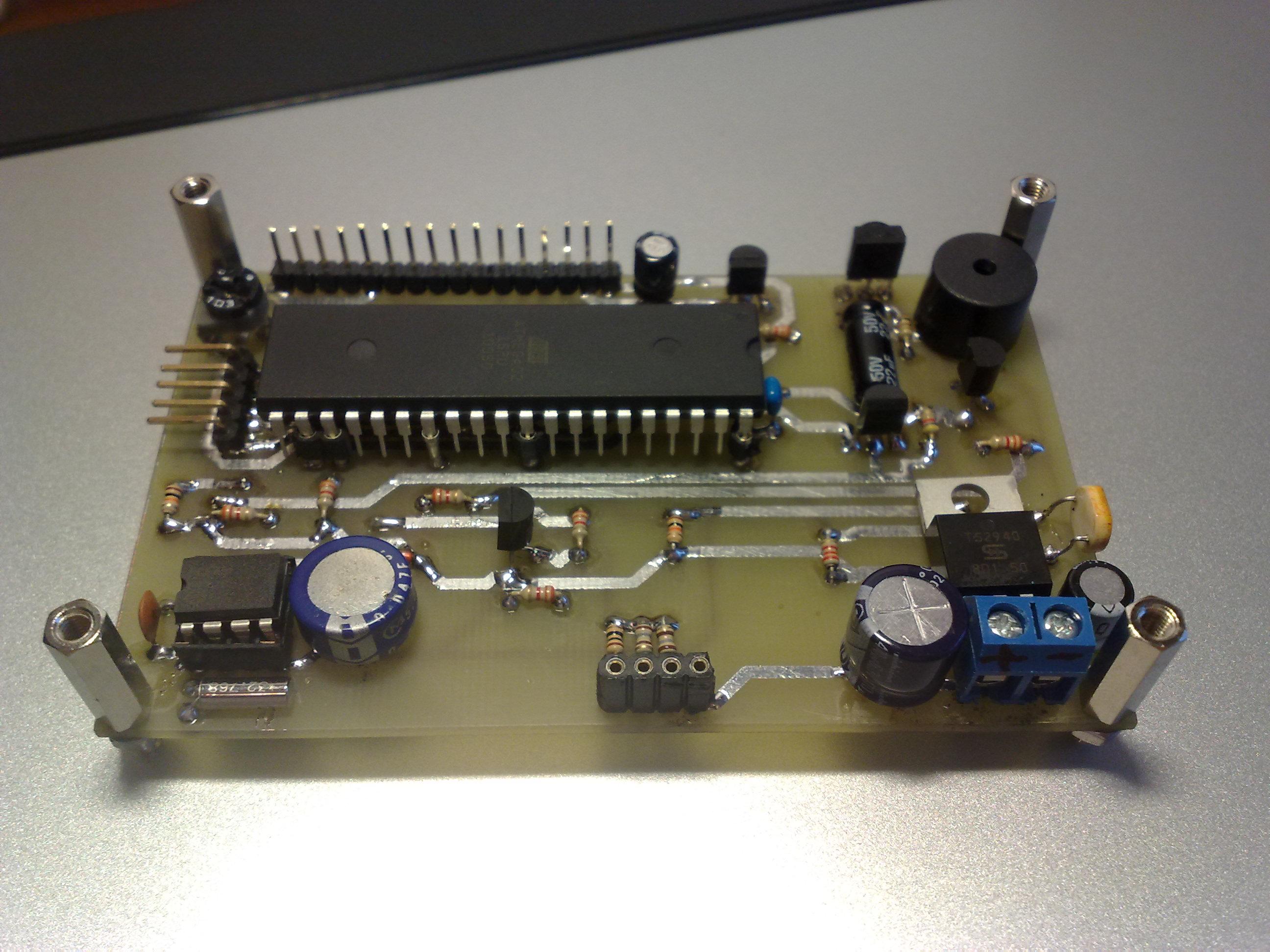
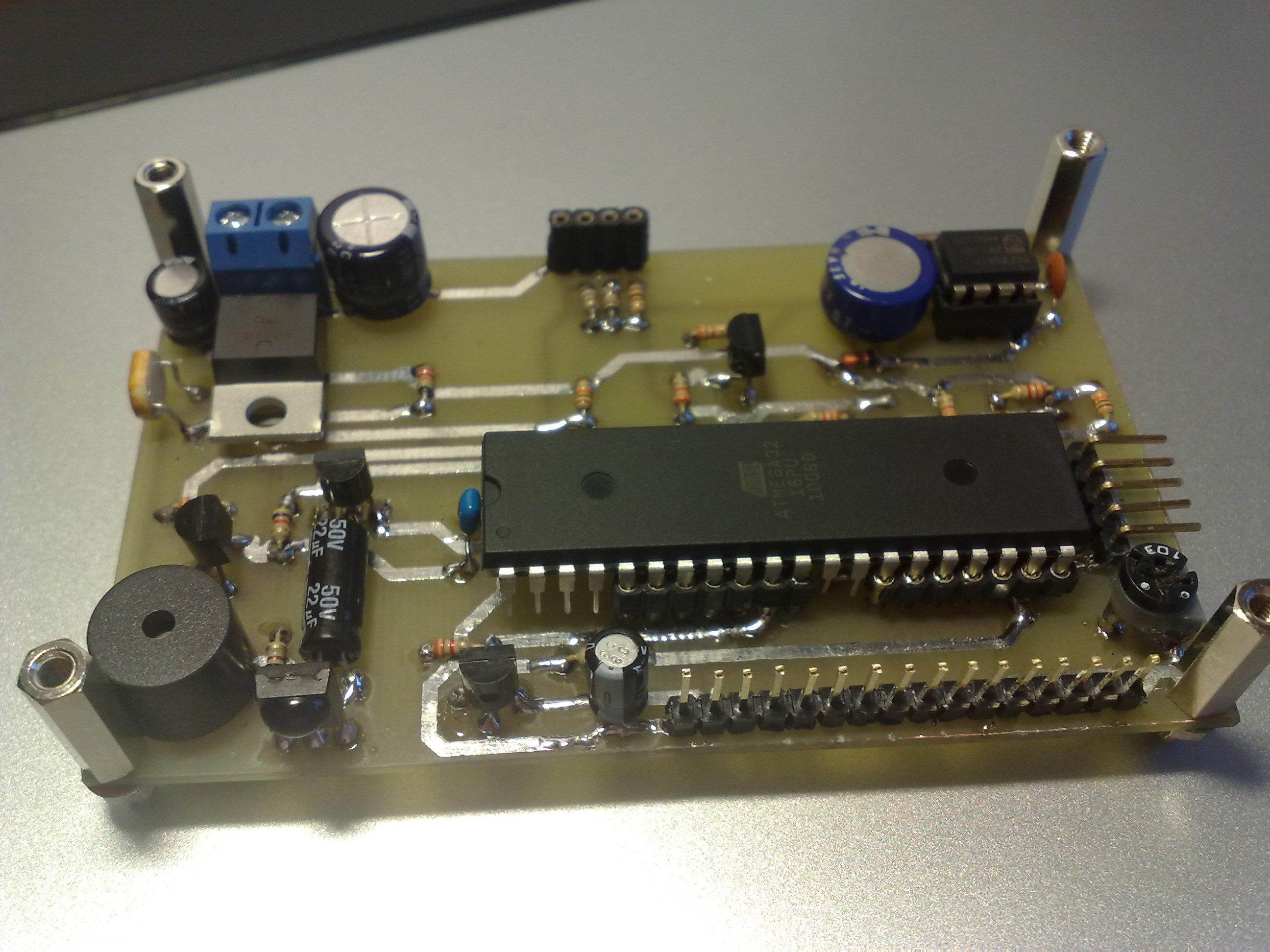
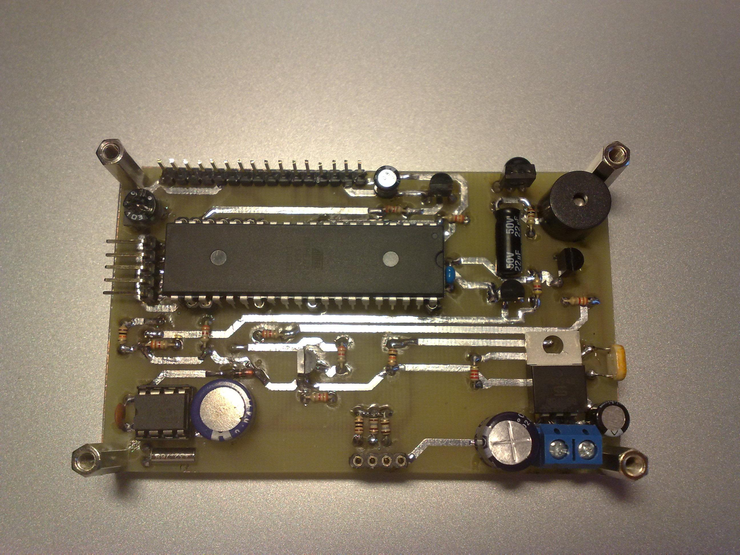
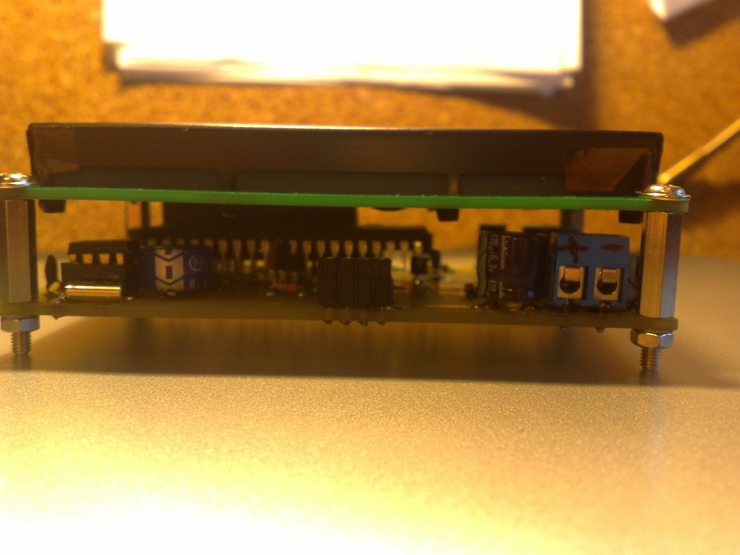
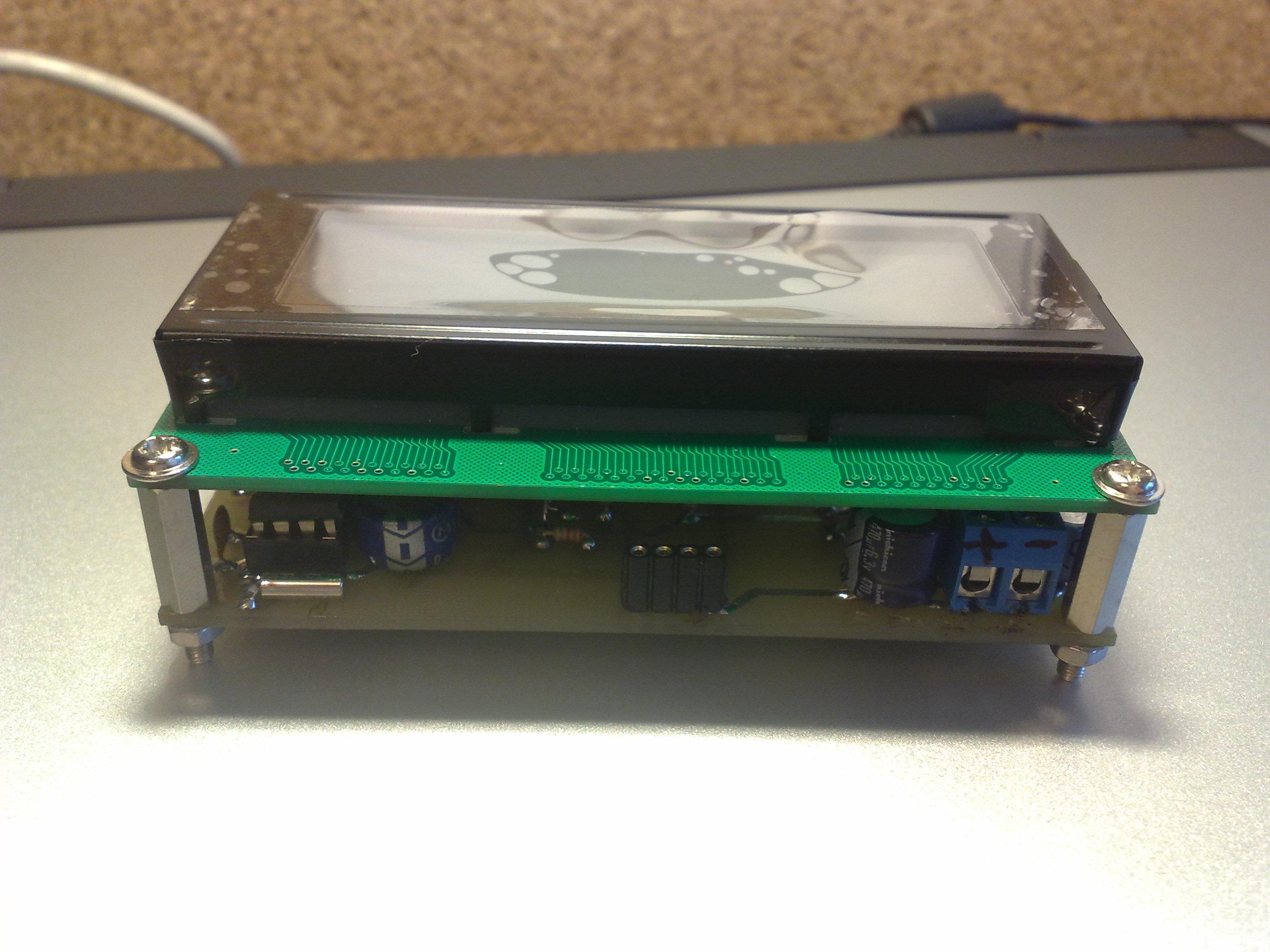
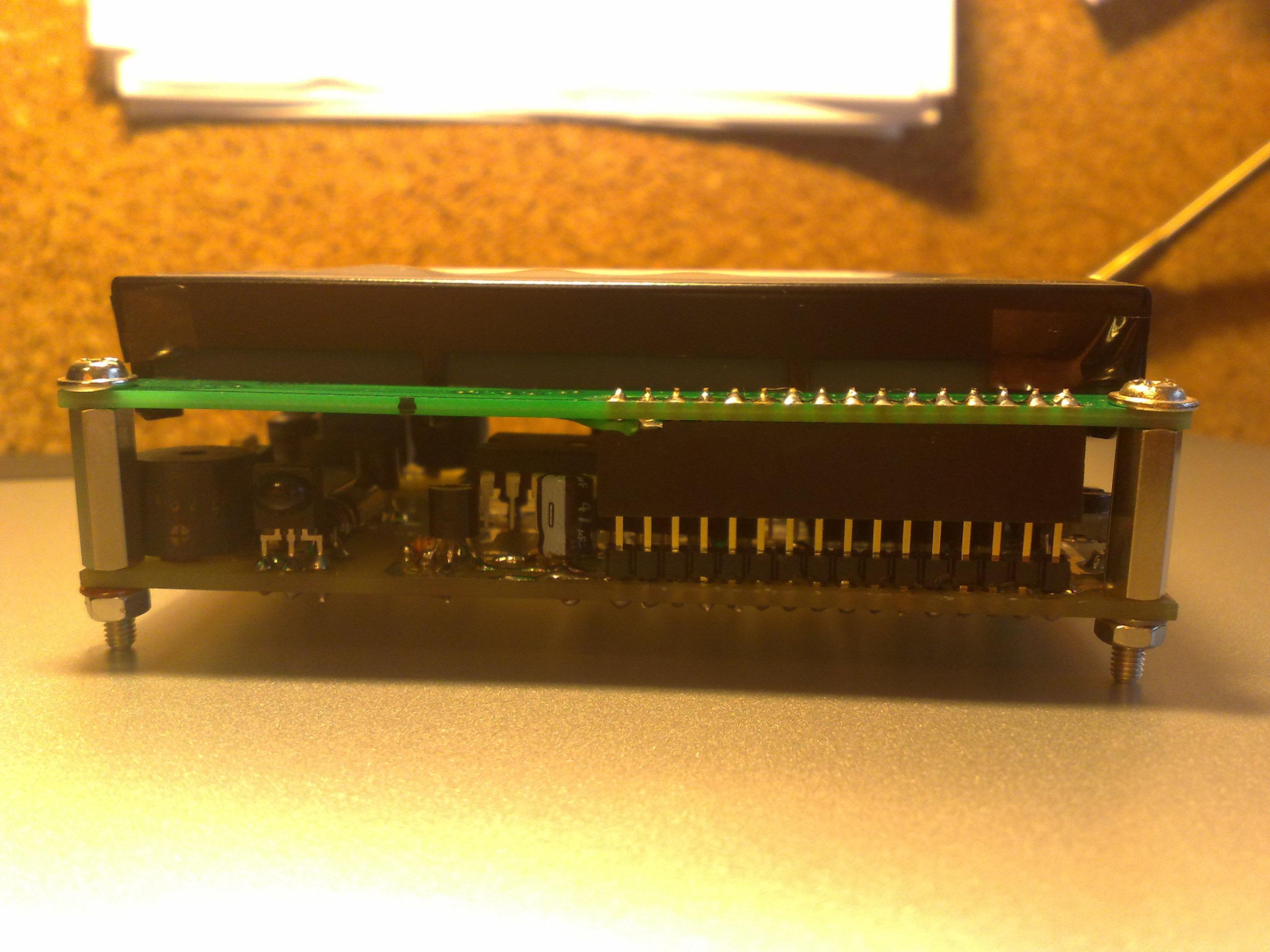
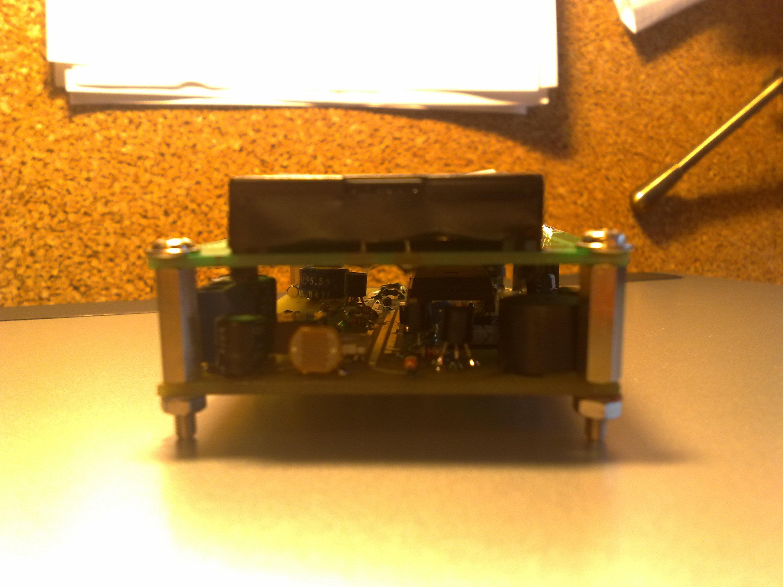
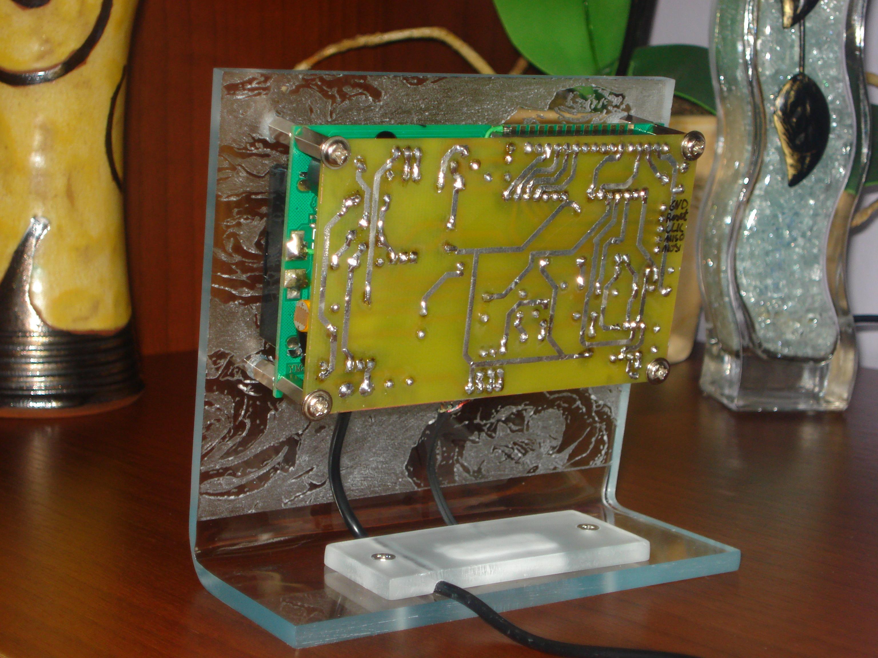
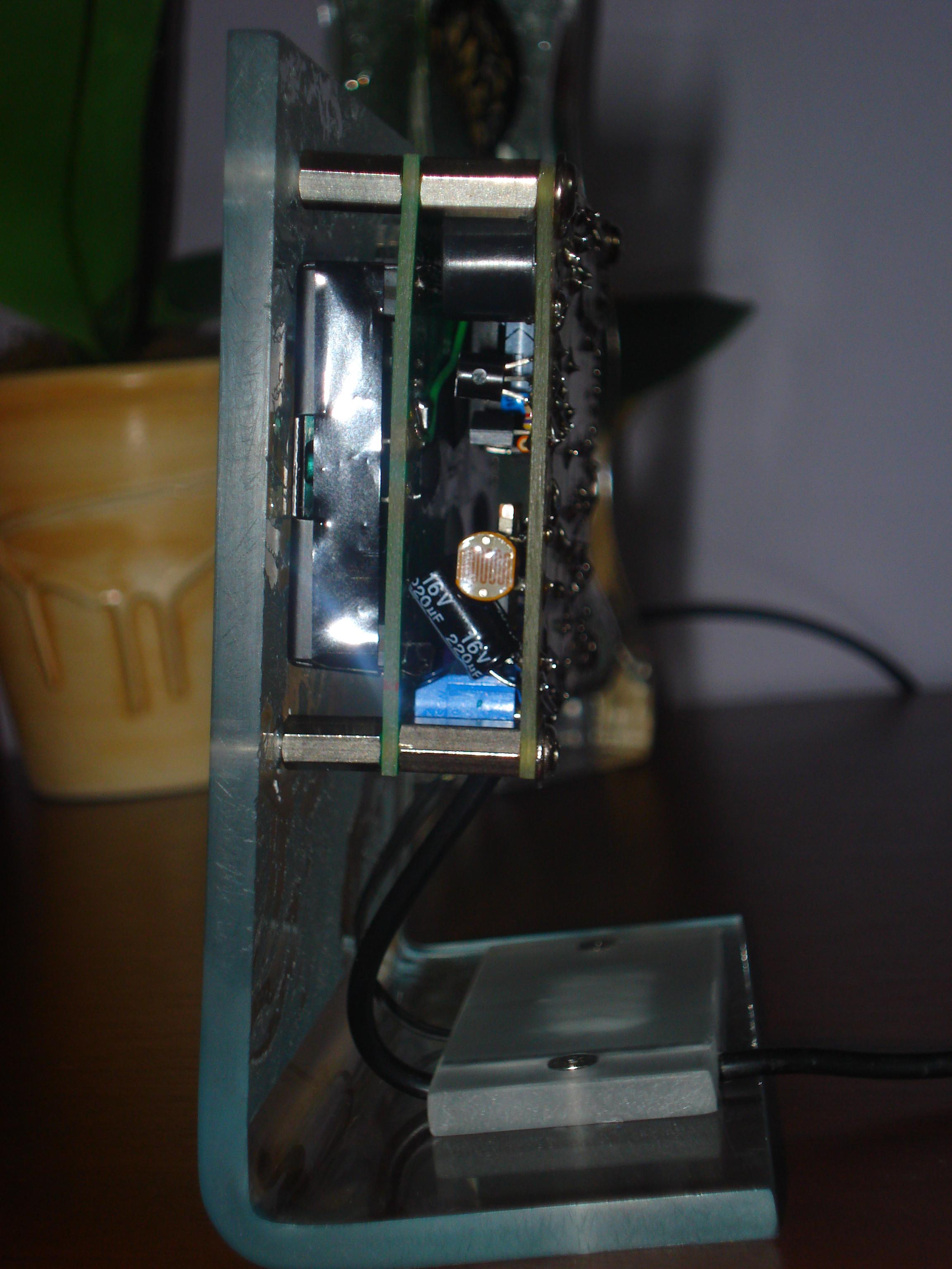
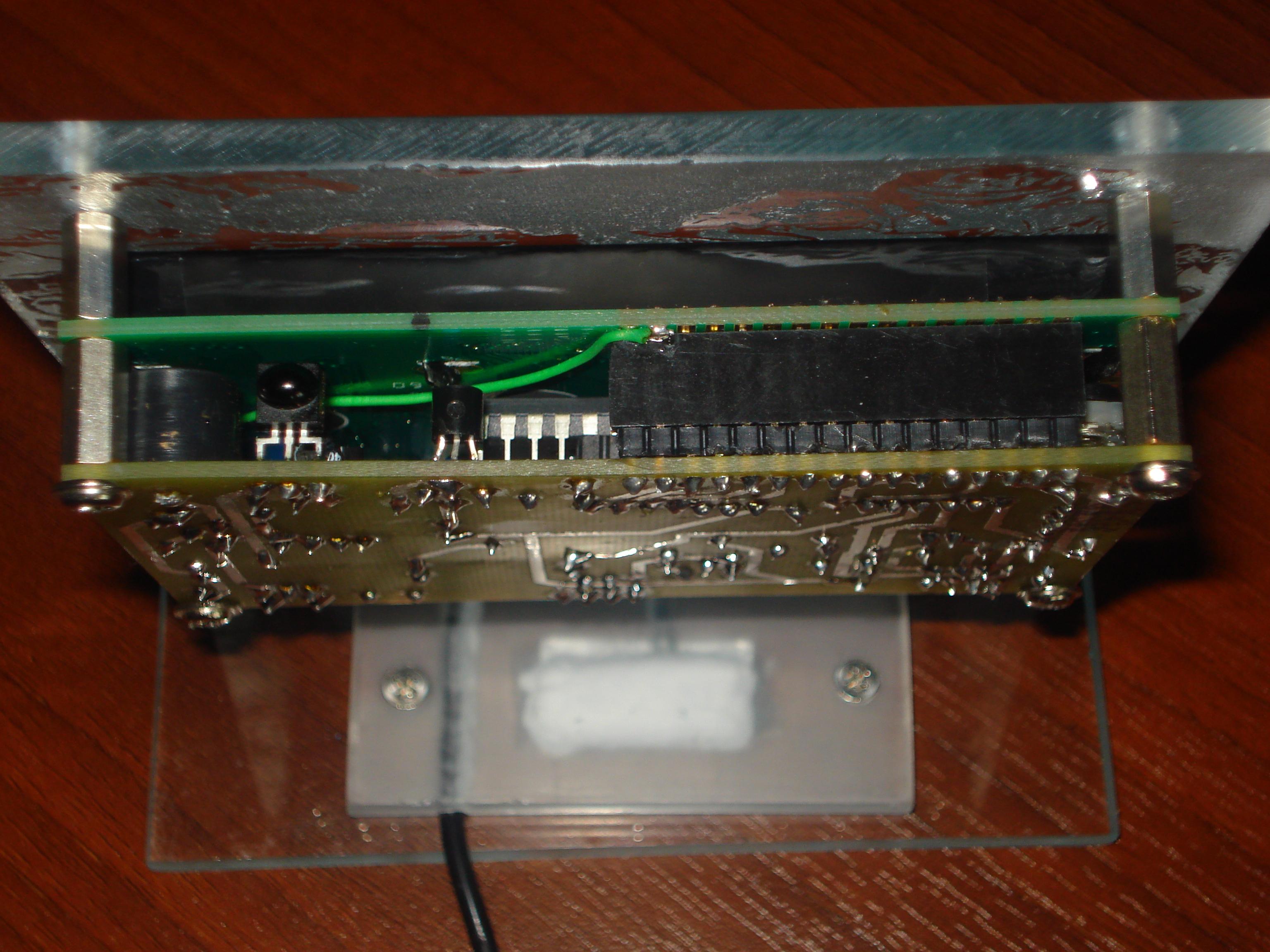
Double sided board was used to make sure that all the elements fit.

Housing is manually engraved and bent using hot air plexiglass. It was illuminated by two white diodes (with 180ohm resistors) and one red diode (with 100ohm resistor). As an effect, you gain nice pink colour.
Pictures of construction:


Link to original thread (useful attachment) – Czasoodmierzacz lub zegar z budzikiem i datą