Sajjadkhan
Full Member level 5
- Joined
- Sep 25, 2010
- Messages
- 307
- Helped
- 17
- Reputation
- 34
- Reaction score
- 16
- Trophy points
- 1,298
- Location
- Rawalpindi,Pakistan
- Activity points
- 4,199
Hi every one.
I have been measuring current at low voltage levels using classic current sense circuit as shown in Fig 1. I am using LM358 series but it can handle single supply voltage up to 32V. As input voltage must be 2V less so i can measure current at 30V. My voltage level goes up to 60V DC.
There are lots of OP-amps and comparators like LT series and AD series which i have seen on websites and also hall effect sensors but unfortunately are unavailable in my Area. LM series are common so if you know a comparator which which can handle high voltages, please let me know.
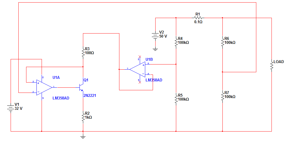
With the existing circuit i worked around a little and managed to get result for high voltage levels. See Fig 2. Using resistors r4,r5,r6,r7(voltage division networks), the voltage across R.sense i.e. 0.1 ohm is reduced to half. U1B is a voltage follower and is used because connecting r3 directly will disturb the voltage division network. Now the problem is that it is working fine on simulation because resistors are set to 0% tolerance and R4, R5, R6 and and R7 are perfectly matched. In real life its not true. When i change value like R4 = 101 k, R56 = 99 k, R6 = 100.5 K and R7 = 100 k, results were not that accurate. For example if SUM of r4 and r5 is even a little bit higher than the sum of r6 and r7 the comparator voltage never goes to zero for 0 amps. Don't know the tolerance effect yet.
So if u guys have any better or robust method the plz guide me, thanks.
I have been measuring current at low voltage levels using classic current sense circuit as shown in Fig 1. I am using LM358 series but it can handle single supply voltage up to 32V. As input voltage must be 2V less so i can measure current at 30V. My voltage level goes up to 60V DC.
There are lots of OP-amps and comparators like LT series and AD series which i have seen on websites and also hall effect sensors but unfortunately are unavailable in my Area. LM series are common so if you know a comparator which which can handle high voltages, please let me know.
With the existing circuit i worked around a little and managed to get result for high voltage levels. See Fig 2. Using resistors r4,r5,r6,r7(voltage division networks), the voltage across R.sense i.e. 0.1 ohm is reduced to half. U1B is a voltage follower and is used because connecting r3 directly will disturb the voltage division network. Now the problem is that it is working fine on simulation because resistors are set to 0% tolerance and R4, R5, R6 and and R7 are perfectly matched. In real life its not true. When i change value like R4 = 101 k, R56 = 99 k, R6 = 100.5 K and R7 = 100 k, results were not that accurate. For example if SUM of r4 and r5 is even a little bit higher than the sum of r6 and r7 the comparator voltage never goes to zero for 0 amps. Don't know the tolerance effect yet.
So if u guys have any better or robust method the plz guide me, thanks.