Bianconero
Newbie level 6

- Joined
- Dec 22, 2014
- Messages
- 11
- Helped
- 1
- Reputation
- 2
- Reaction score
- 1
- Trophy points
- 3
- Activity points
- 92
Hi, I designed a simple half bridge circuit using popular FET driver IR2101 (switching freq. around 500 Hz, drain current about 250 mA, supply voltage about 12 V):

Of course I have resistive load connected between the VS node and ground, just forgot to draw it.
This is a part of a bigger schematic, but the bridge circuit doesn't work as I expected. When the high side FET is on, the voltage drop across it (drain-source voltage) is about 2.1 V. When the low side FET is ON, everything is OK - the Vds voltage of it is around 0 V.
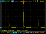
Voltage between LO and GND looks pretty good - a square wave from 0 to 12 V. Voltage between HO and VS looks exactly like this:

I guess that the problem is caused by improper driving the high side, ie. the bootstrap circuit. The gate voltage drops and the high side FET works in its linear region. What could I do to force it to saturate? Is the 1k G-S resistor a problem? I read that there should be such resistor to prevent FETs from various failure types.

Of course I have resistive load connected between the VS node and ground, just forgot to draw it.
This is a part of a bigger schematic, but the bridge circuit doesn't work as I expected. When the high side FET is on, the voltage drop across it (drain-source voltage) is about 2.1 V. When the low side FET is ON, everything is OK - the Vds voltage of it is around 0 V.
Voltage between LO and GND looks pretty good - a square wave from 0 to 12 V. Voltage between HO and VS looks exactly like this:

I guess that the problem is caused by improper driving the high side, ie. the bootstrap circuit. The gate voltage drops and the high side FET works in its linear region. What could I do to force it to saturate? Is the 1k G-S resistor a problem? I read that there should be such resistor to prevent FETs from various failure types.
Last edited:


