mrinalmani
Advanced Member level 1

- Joined
- Oct 7, 2011
- Messages
- 467
- Helped
- 60
- Reputation
- 121
- Reaction score
- 59
- Trophy points
- 1,318
- Location
- Delhi, India
- Activity points
- 5,348
My application requires MOSFET switching (Cgs = 2000pF) at approximately 150kHz. The duty cycle may go down to 15% and thus a typical switch ON-OFF interval my reach as low as 1us.
Although motivated from the requirements stated above, I have certain questions that are general for any switching application.
1. OPTOCOUPLERS
Opto-couplers seem to have large switching delays (0.5us to 2us), but I find many posts suggesting their use for high speed application. How can this be explained? Are opto-couplers suitable for speeds as high as 150kHz?
2. PULSE-TRANSFORMERS
I also find posts strongly recommending pulse-transformers for high-speed applications. But the transformer seems to have a leakage inductance figuring around 300nH to 1uH. This should severely limit the rise time of the pulse. How can their use be justified. What are the techniques for improving their response time.
3. DRIVER-IC
Driver ICs seem to have an answer, but they are expensive, and all the more expensive for tight switching delays. So their use is temporarily being suspended and perhaps permanently if another cost-effective solution can be found. (please bear in mind "mass -production", each dollar counts)
4. DISCRETE COMPONENT VERSION OF DRIVER IC
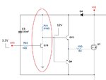
I am strongly looking forward to design a gate driver out of discrete components only. I successfully made one for a 12V HBridge. Now I need to make one for 600V. This voltage requirement creates an immediate difficulty. Consider the attachment below.... (simplified circuit)
(a) First things first, I intend Q10 to act as a level shifter. It is transforming a 3.3V input to 12V. Please note that this 12V is with respect to the floating ground and 3.3V is wrt. the actual ground. Is this what level shifters are required to do? Or do they level-shift voltages wrt to the same original ground?
(b) If instead of 12V we had 600V, then firstly, Q10 would have to be of 600V and not merely 20-30V. Secondly, even small amount of current through Q10 would cause large power losses. Now, what makes the driver IC's level shifting so efficient even at high voltages. How do they implement it?
(c) Consider when Q10 is ON. It will pull down the totem-pole input voltage to zero. But we do not want it to go to 0. We simply want it to be pulled down to the level of the floating ground. If it is pulled to zero then we would have a -600V across the totem input! How to go about this problem? (Please note that in a H-Bridge this situation does not occur because as soon as the high-side MOSFET is turned off, the low-side MOSFET if turned on, and thus the floating ground is pulled down to zero and does not remain at 600V)
All suggestions would be deeply appreciated...
Although motivated from the requirements stated above, I have certain questions that are general for any switching application.
1. OPTOCOUPLERS
Opto-couplers seem to have large switching delays (0.5us to 2us), but I find many posts suggesting their use for high speed application. How can this be explained? Are opto-couplers suitable for speeds as high as 150kHz?
2. PULSE-TRANSFORMERS
I also find posts strongly recommending pulse-transformers for high-speed applications. But the transformer seems to have a leakage inductance figuring around 300nH to 1uH. This should severely limit the rise time of the pulse. How can their use be justified. What are the techniques for improving their response time.
3. DRIVER-IC
Driver ICs seem to have an answer, but they are expensive, and all the more expensive for tight switching delays. So their use is temporarily being suspended and perhaps permanently if another cost-effective solution can be found. (please bear in mind "mass -production", each dollar counts)
4. DISCRETE COMPONENT VERSION OF DRIVER IC
I am strongly looking forward to design a gate driver out of discrete components only. I successfully made one for a 12V HBridge. Now I need to make one for 600V. This voltage requirement creates an immediate difficulty. Consider the attachment below.... (simplified circuit)
(a) First things first, I intend Q10 to act as a level shifter. It is transforming a 3.3V input to 12V. Please note that this 12V is with respect to the floating ground and 3.3V is wrt. the actual ground. Is this what level shifters are required to do? Or do they level-shift voltages wrt to the same original ground?
(b) If instead of 12V we had 600V, then firstly, Q10 would have to be of 600V and not merely 20-30V. Secondly, even small amount of current through Q10 would cause large power losses. Now, what makes the driver IC's level shifting so efficient even at high voltages. How do they implement it?
(c) Consider when Q10 is ON. It will pull down the totem-pole input voltage to zero. But we do not want it to go to 0. We simply want it to be pulled down to the level of the floating ground. If it is pulled to zero then we would have a -600V across the totem input! How to go about this problem? (Please note that in a H-Bridge this situation does not occur because as soon as the high-side MOSFET is turned off, the low-side MOSFET if turned on, and thus the floating ground is pulled down to zero and does not remain at 600V)
All suggestions would be deeply appreciated...
Attachments
Last edited:

