Continue to Site

Welcome to EDAboard.com

Welcome to our site! EDAboard.com is an international Electronics Discussion Forum focused on EDA software, circuits, schematics, books, theory, papers, asic, pld, 8051, DSP, Network, RF, Analog Design, PCB, Service Manuals... and a whole lot more! To participate you need to register. Registration is free. Click here to register now.

High pulse at Vin and Vout

Status
Not open for further replies.

kakiitek

Junior Member level 1
Joined
Sep 10, 2020
Messages
17
Helped
0
Reputation
0
Reaction score
0
Trophy points
1
Activity points
173
Hi all,
I have configured a buck converter TPS53319 for the conversion Vin=16V to Vout=0.70V. We will be drawing a maximum of 5A.
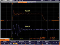
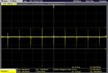
While the output ripple is within expectation <50mVpp, we observed a pulse at both the Vin and Vout. This pulse is about 600mVpp at Vin and 80Vpp at Vout. The pulse interval is the same as the switching frequency of 500kHz.

My understanding is that this pulse occured at Vin due to insufficient Cin. Increasing the Cin with 3x 47uF (2012) reduces the pulse at Vin to 400mVpp. However this does not result in significant reduction of the pulse at Vout. Could anyone enlighten me on how we could resolve this?
How do I reduce the pulse at Vin further?

The attachment below shows the pulse at Vin.
Vout has similar pulse but with Vpp around 80mVpp.

Many thanks!
 

Attachments

  • 1622125060280_IMG-20210527-WA0018.jpg
    1622125060280_IMG-20210527-WA0018.jpg
    38.6 KB · Views: 102
Last edited:

You have conformed to the datasheet ceramic capacitor constraints on the output ?

Layout of power rails and ground minimum parasitic L ?

Post your schematic and breadboard/layout...

Your scope probing appropriate -


Regards, Dana.
 

Hi,

in best case it is a mesurement artefact.

But maybe a true issue like:
* bad PCB layout
* wrong / unsuitable capacitors

Klaus
 
Learn about common mode effect and how this is affecting your measurements

short the probe and gnd clip on your scope and place on the +ve out - you should see Zero - what do you see ... ?
 

    Kajunbee

    Points: 2
    Helpful Answer Positive Rating

    kakiitek

    Points: 2
    Helpful Answer Positive Rating
Hi all,
Many thanks for the response.
The probe is good. The overshooting occurs when I am loading the regulator above 1.0A. The circuit has no issue providing a stable Vout up to 5.0A with minimal ripple. But of course, the same spike is shown at Vout as well. Attached is the latest scope reading.
The Brown trace is a trace measured at the inductor under DC mode.
The Blue trace is measured at the Vin under AC mode to observe the pulse.
What would be the main issue that causes the spike at the Vin and the Overshoot at the switching?
Could this be due to inadequate Cin? I have added up to 3x 47uF as Cin with a slight reduction in the overshooting.
Anything else I could do to reduce the it? Thank you.
Rgds,
kakiitek
 

Attachments

  • Plot1.jpg
    Plot1.jpg
    44.5 KB · Views: 90

HI,

you neither refer to my nor Easy Peasy´s post.

post:
* your PCB layout (a schematic isn´t much of use)
* a photo where and how you attached the probes on the PCB... the GND connection is same important than the signal connection.
* give the exact vendor and part number of the used capacitors (the capacitance value alone gives not much information)
* show a scope picture with Easy Peasy´s test recommendation

Klaus
 
Hi Guys, many thanks for the suggestion, but I could not provide such details at this point of time. Understand that it will be difficult for you to help me without such information. My apologies.
One last question though, by bandwidth limiting the oscilloscope to 20MHz, the spike could not be observed. Do we interpret this as a harmless noise which we can safely ignore? Many thanks for you guidance on this.
Best rgds,
kakiitek
 

do you know how to set up your scope probe using the 5v square wave on the scope?
Yes, verified that. It is a clean 1VDC at 1kHz frequency.
--- Updated ---

Currently all measurements is made by disconnecting the regulator from onboard load and connecting the regulator output through three feets of wires to an external electronic load. With all the clips and dangling wires, it will be hard to get proper measurements of noise and ripples. Thanks!
 
Last edited:

Status
Not open for further replies.

Part and Inventory Search

Welcome to EDABoard.com

Sponsor

Back
Top