viperpaki007
Full Member level 5

- Joined
- Jul 2, 2008
- Messages
- 274
- Helped
- 11
- Reputation
- 22
- Reaction score
- 8
- Trophy points
- 1,298
- Location
- Finland
- Activity points
- 3,437
Hi,
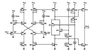
I need to design opamp which can deliver upto 600mA of output current, Vdd=4.2V, and peak to peak output voltage swing from 3.5V to 0.5V. I am using 1V gate oxide breakdown transistors.
I found the following circuit in [1] and authors have claimed high output current delivering ability. However, i am not able to completly understand this circuit. Few things are clear though. M9,M10, M2, M3, M7 ,M6, M11 and M12 form input differential stage. While M18 and M17 form output class AB structure. Rest of the circuit is unclear to me. Can somebody explain how the circuit works. Moreover, how i will be able to meet gateoxide break down conditions for M17 and M18 transistors.

[1] M.hassan, A combined series-parallel hybrid env-amp for env-tracking mobile terminal, IEEE journal solid state circuits, 2012
I need to design opamp which can deliver upto 600mA of output current, Vdd=4.2V, and peak to peak output voltage swing from 3.5V to 0.5V. I am using 1V gate oxide breakdown transistors.
I found the following circuit in [1] and authors have claimed high output current delivering ability. However, i am not able to completly understand this circuit. Few things are clear though. M9,M10, M2, M3, M7 ,M6, M11 and M12 form input differential stage. While M18 and M17 form output class AB structure. Rest of the circuit is unclear to me. Can somebody explain how the circuit works. Moreover, how i will be able to meet gateoxide break down conditions for M17 and M18 transistors.

[1] M.hassan, A combined series-parallel hybrid env-amp for env-tracking mobile terminal, IEEE journal solid state circuits, 2012

