boylesg
Advanced Member level 4

- Joined
- Jul 15, 2012
- Messages
- 1,023
- Helped
- 5
- Reputation
- 10
- Reaction score
- 6
- Trophy points
- 1,318
- Location
- Epping, Victoria, Australia
- Activity points
- 11,697
Does anyone have a specific example of this?
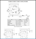
I am looking at the example in the datasheet but there are no specifics regarding the transistor:

Do you do the MC34063 calculation for base current of your selected transistor at saturation?
Usually the base to GND resistor is 10x the value of the series base resistor. But in this case there is no series base resistor so what value do I multiply by 10?
Is the output capacitor in the NPN schematic the same as Co in the non boosted schematic? Or, in the NPN boosted schematic, is Co unnecessary and C is determined by a different calculation?
I am looking at the example in the datasheet but there are no specifics regarding the transistor:

Do you do the MC34063 calculation for base current of your selected transistor at saturation?
Usually the base to GND resistor is 10x the value of the series base resistor. But in this case there is no series base resistor so what value do I multiply by 10?
Is the output capacitor in the NPN schematic the same as Co in the non boosted schematic? Or, in the NPN boosted schematic, is Co unnecessary and C is determined by a different calculation?

