Continue to Site

Welcome to EDAboard.com

Welcome to our site! EDAboard.com is an international Electronics Discussion Forum focused on EDA software, circuits, schematics, books, theory, papers, asic, pld, 8051, DSP, Network, RF, Analog Design, PCB, Service Manuals... and a whole lot more! To participate you need to register. Registration is free. Click here to register now.

HFSS: Unphysical results when simulating waveguides

Status
Not open for further replies.

cwin

Newbie level 5
Joined
Aug 6, 2014
Messages
10
Helped
1
Reputation
2
Reaction score
1
Trophy points
3
Activity points
76
I've only recently started using HFSS and I've noticed that sometimes I get strange, unphysical fields and solutions.
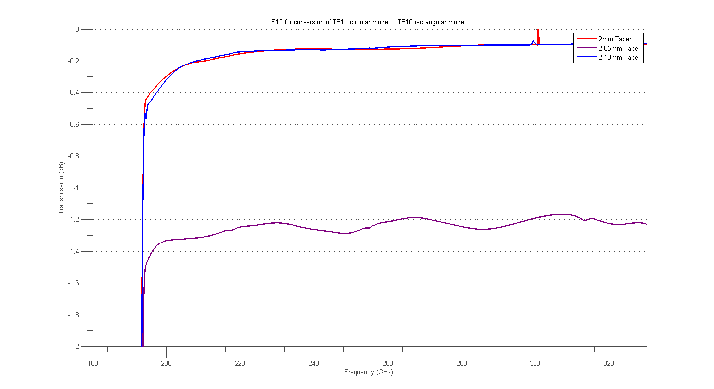
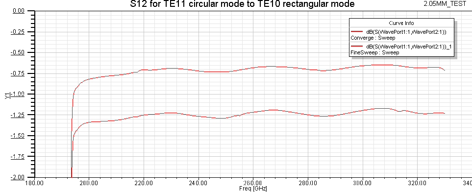
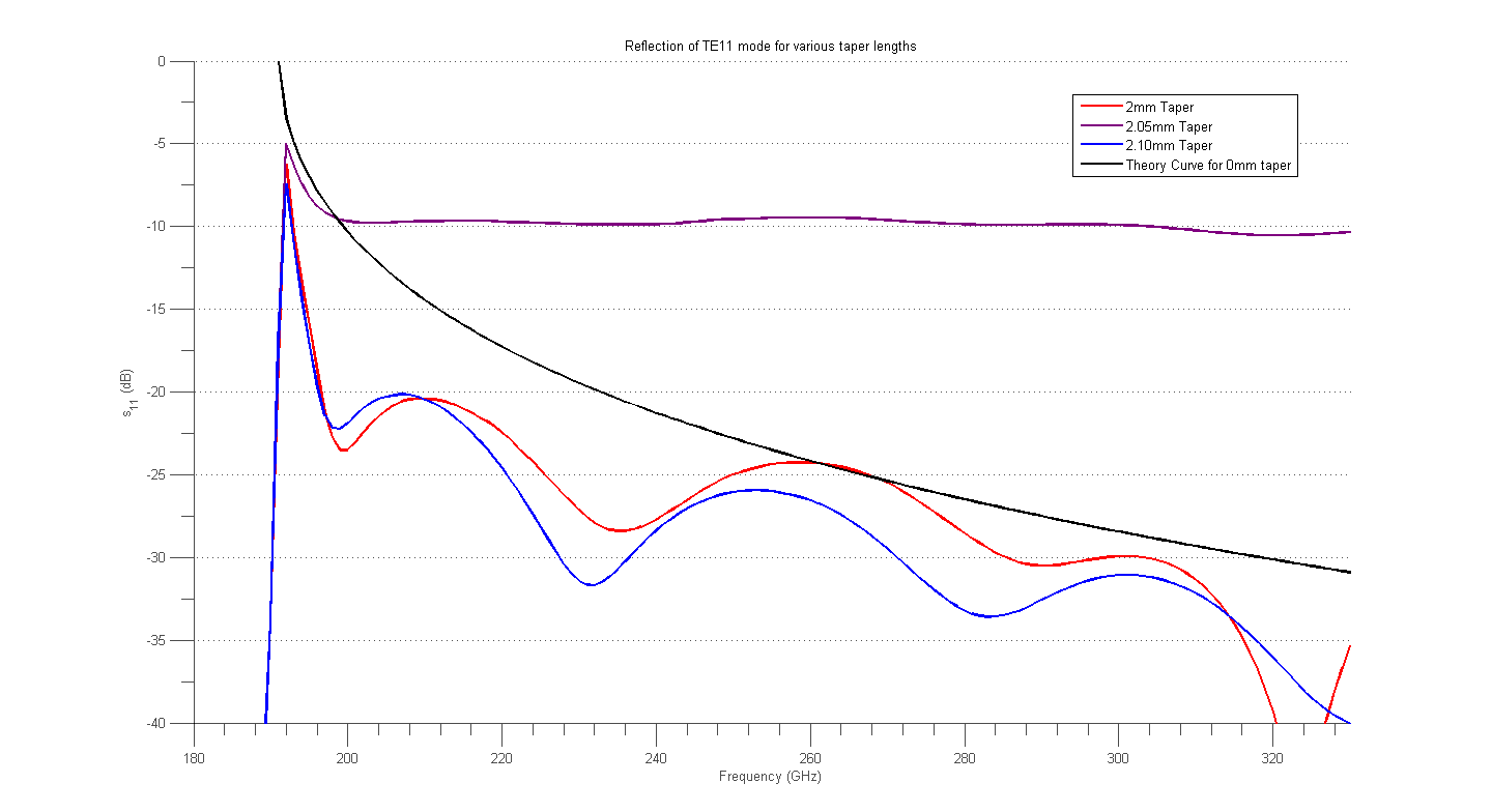
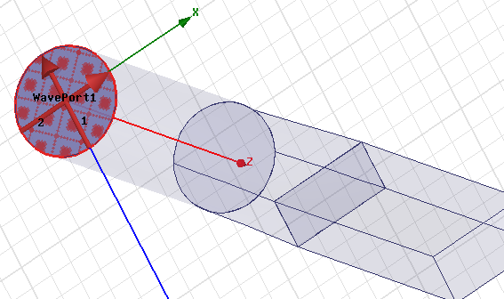
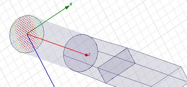
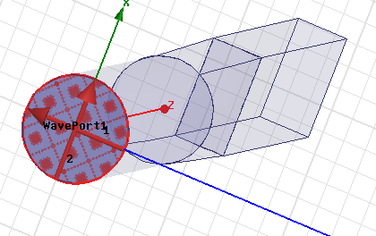
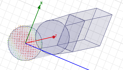
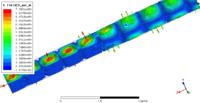
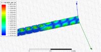
For example I'm simulating a transition of the TE11 mode in a circular waveguide into a TE10 mode in a rectangular waveguide. Below are two animations of this transition. The only difference between the two is the length of the taper, the first being 2mm in length and the second being 2.05mm in length. Simulations with taper length 2.1mm show a physically agreeable fields consistent with the 2mm simulation.


The circular waveguide has a radius of .46mm and transitions to a .9x.45mm rectangular waveguide.
The walls has conductivity 4.7e7 S/m.

My solution setup is:
Solution Freq: 250GHz
Adaptive Solution with Maximum number of Passes:6 with maximum delta S: 0.02.

I'm still learning the ropes of HFSS so let me know if there's something I completely over looked or if there's some tests I can run to pinpoint the cause of this strange effect.


The simulation produces similar results when we make a slight change in geometry but when we pick a value in between we get vastly different results. It's hard for me to believe that the physics is actually that sensitive to the initial conditions so I'm skeptical of the simulated results. Here are some graphs that describe this process.

The first graph shows the S12 for various taper lengths. We see similar results for 2mm and 2.1mm but vastly different results for 2.05mm. The second graph shows S12 for the 2.05mm taper but compares two different solution setups. One is the default lambda refinement of 0.333. The other has lambda refinement of 0.1. It's suspicious that the two produces different results.

- - - Updated - - -

 
Last edited:

For the 2mm taper:
2 out of 6 passes with max mag. delta S = 0.00656 and total tetrahedra = 5493

For the 2.1mm taper:
2 out of 6 passes with max mag. delta S = 0.0179 and total tetrahedra = 5990

For the 2.05mm taper with lambda = 0.33
3 out of 6 passes with max mag. delta S = 0.0040 and total tetrahedra = 6822

For the 2.05mm taper with lambda = 0.1
3 out of 6 passes with max mag. delta S = 0.0025 and total tetrahedra = 27837
 

Hi cwin.

Therein lies the answer, I think. The 2.05mm does 3 passes instead of 2, and has 27837 tetrahedra as compared to 5990. I would specify at least 3 converged passes (with a delta S < 0.01) and re-run all of these cases. My guess is the 2.05mm is the only correct solution.
 

I've reran the simulation with refined surface approx. mesh, max delta S = 0.01 and a minimum converged passes of 3. Unfortunately the results look about the same. Just some stats about the solutions:

2.0mm taper: 5 passes with 19346 tetrahedra and max delta S of 0.00093
2.05mm taper: 4 passes with 17494 tetrahedra and max delta S of 0.00108
2.1mm taper: 4 passes with 18018 tetrahedra and max delta S of 0.00188

I'm inclined to believe the results of 2.0mm and the 2.1mm taper. Just doing a quick calculation computing the reflection of the first mode due to the impedance mismatch from the circular waveguide (r = .46mm) to the rectangular waveguide (a = 0.9mm) we get the results below plotted with s11. For 2.0mm and 2.1mm it makes sense that reflection is a little better than the discontinuous case.

It's frustrating that I'm getting these results because I'm certain something small is off that is causing dramatically different results. I've checked that the ports are defined/aligned correctly, that the meshes are comparable for the three and there isn't some small defect in the geometry. I'm open to any suggestions or tests I can perform.
 

I think I figured out the issue. When I was defining my ports I stuck to the default options and was unaware that the integration line does not align the modes. Just to illustrate this in case someone else ever comes across this problem I've attached some images below. The first two images are my port definitions and the field lines for the first mode for my 2.00mm taper. The third and fourth images are the same for my 2.05mm taper. The TE11 mode was off-axis from my integration line for both cases but the 2.00mm was much closer to what I intended than the 2.05mm taper resulting in the strange results above. My modes for the 2.1mm taper was similar to the 2.00mm taper.


Status
Not open for further replies.

Part and Inventory Search

Welcome to EDABoard.com

Sponsor

Back
Top