Continue to Site

Welcome to EDAboard.com

Welcome to our site! EDAboard.com is an international Electronics Discussion Forum focused on EDA software, circuits, schematics, books, theory, papers, asic, pld, 8051, DSP, Network, RF, Analog Design, PCB, Service Manuals... and a whole lot more! To participate you need to register. Registration is free. Click here to register now.

[SOLVED] HFSS Help (Urgent ).

Status
Not open for further replies.
Dear jeeudr,

please upload one example of aperture feed patch antenna.
thank you.
 

sir,
feeding point is same location in microstrip inset feed, coax feed, aperture feed. Is it right ?
 

for microstrip inset and coax: yes, the impedance is determined by feed point location

for aperture feed: I do not know
 

Dear Sir,

what is the affect of gaping between patch and inset microstrip feed and how can we take that value(Wf)?
 

Attachments

  • inset microstrip feed.jpg
    inset microstrip feed.jpg
    20.2 KB · Views: 74

there is always an error Guys !!

i don't understand the Concept itself ,...

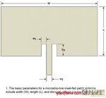
How To feed This antenna ( Rectangle between the antenna and ground and assign it as wave port !)
or i should simulate a Coaxcail cable ( Feed pin + coax pin + Coax + port cap ) !!


This is The antenna and the paper with out feed ,..please Help me with the Feed

View attachment 89495


That's It dear / jeeudr
 

I got warning which is given below.
"Boundary PerfE1 is an infinite ground but does not touch a radiation surface."
please help me to resolve that warning.
thank you.
 

I got warning which is given below.
"Boundary PerfE1 is an infinite ground but does not touch a radiation surface."
please help me to resolve that warning.
thank you.


For which file ? The one I uploaded in post #20 does not have any warnings.

If it is some other file, then, to remove that warning, leave the 'Infinite Ground Plane' option unchecked when you apply the PerfE boundary condition.


That's It dear / jeeudr
It is an interesting design to cover multiple bands. You can simulated the attached file which demonstrates this. I suspect that the radiation pattern / gain is not very uniform though.
 

Attachments

  • Help.zip
    31.9 KB · Views: 80
Last edited:
I made the following changes:

1. Added a rectangle between the gap of the ground plane and the antenna feed point and assigned it an excitation (lumped port). This is for the purpose of measuring the power reflections / S11 / VSWR
2. Added an external boundary for entire structure: a box which is atleast 15 cm (i.e. lambda/4 of 0.5 GHz) away from the radiating structure. Applied the radiating boundary condition on the faces of this box. This is for the purpose of measuring radiated fields.
3. Adaptive solution frequency set to 3 GHz and a fast sweep from 0.5 GHz to 3 GHz was also setup. Only fast / discrete can compute the fields in the sweep. Interpolating will not give you the radiated fields at all frequencies.
4. Added an infinite sphere in the radiation setup for calculation of far field. Also, added a field overlay of surface current to reproduce one of the plots from the paper you provided.
5. After this, I just modified your reports files to show the dB(S11) and VSWR correctly.

1 - 3 are essential.
4 - 5 is just something like post-processing to observe more information from the solution.

Try to search for tutorials or workshop lectures on HFSS antenna design. I think that even this forum has many files (buried in different threads) on how to set up simulations in HFSS.
 
Status
Not open for further replies.

Similar threads

Part and Inventory Search

Welcome to EDABoard.com

Sponsor

Back
Top