Continue to Site

Welcome to EDAboard.com

Welcome to our site! EDAboard.com is an international Electronics Discussion Forum focused on EDA software, circuits, schematics, books, theory, papers, asic, pld, 8051, DSP, Network, RF, Analog Design, PCB, Service Manuals... and a whole lot more! To participate you need to register. Registration is free. Click here to register now.

HFSS Help: how to deal with the port to port capacitive coupling?

Status
Not open for further replies.

cmosbjt

Full Member level 5
Full Member level 5
Joined
Apr 25, 2004
Messages
250
Helped
10
Reputation
20
Reaction score
2
Trophy points
1,298
Location
USA
Activity points
2,293
Hi All,

In HFSS, I am using Lumped Ports. I found that the capacitive coupling between ports are big.
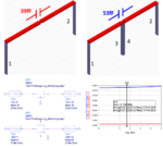
I attached an HFSS project file here. I am simulating the capacitance between two metal traces.
In the first setup, I have only 2 ports at each end of traces. In the second setup, I added two more
ports that are very close to each other. After HFSS EM sim, I extract the snp and put them in ADS
to extract the parasitic capacitor from 2 port Y parameters. The first case gives 39fF and the second
case gives 53fF. The difference is rather big, 36% !

My question is, how to avoid/remove/calibrate out the port to port coupling? In a lot of cases, we need to
use many ports in the EM setup, and those ports have coupling to each other, then the EM becomes
less accurate as more ports are used.

Please help. Thanks a lot.
PortCapCoupling.png
 

Attachments

  • PortCouplingCap.rar
    35.7 KB · Views: 99
  • PortCapCoupling.gif
    PortCapCoupling.gif
    33.9 KB · Views: 242

That's where the planar solvers (Momentum, Sonnet etc..) are much more advanced, and offer various port calibration schemes.

In your case, you could manually de-embed the parasitic capacitance. Create a testcase where you simuate the via metal (as used for port 3/4) but without connecting it to the bottom ground, and without ports 3/4. So just leave a small gap at the bottom, so that this via metal forms a capacitor. Then, you can extract the capacitance contribution between these vias.

However, you are not finished yet. The current in this via metal at port 3/4 has magnetic coupling also. You need to calculate the inductance of each individual via, and also the mutual inductance between the vias. Mutual inductance in these configurations causes the total inductance to be smaller than 2 * individual vias, because the field partially compensates.
 

Thanks for your reply. I am wondering if there is more practical way to handle this?
I mean Ansoft must have been aware of this issue for a long time, have they done anything to deal with it?
 

Thanks for your reply. I am wondering if there is more practical way to handle this?
I mean Ansoft must have been aware of this issue for a long time, have they done anything to deal with it?

For most users, HFSS is considered the wrong tool for this application, and instead planar solver are used (more efficient and accurate for this type of work).
 

For most users, HFSS is considered the wrong tool for this application, and instead planar solver are used (more efficient and accurate for this type of work).

Do you think Q3D uses planar solver? since it comes from Ansoft as well, I think it would be easier to switch to. How good / accurate do you think Q3D is comparing with Momentum or Sonnet? Thanks.
 

How good / accurate do you think Q3D is comparing with Momentum or Sonnet? Thanks.

I have not come across Q3D for this type of work. No idea what type of port calibration they might have.
 

any other thoughts on this issue? Thanks.
 

Status
Not open for further replies.

Part and Inventory Search

Welcome to EDABoard.com

Sponsor

Back
Top