qqpost
Member level 1
Hi everyone,
I'm new to HFSS and I have questions about the airbox. My understanding and questions are just as follows. Hope you can point out my fault and any discussion on the topic is welcomed.
As to my knowledge, the airbox is an artificial boundary that one set to separate the model structure with the outer perfect electric conductor(PEC). If there isn't an airbox, the structure will perform like inside a metal box and the electrical field will reflect when it touches the box, which not want to be seen in the simulation. So that's why we need a airbox that large enough to not infect the distribution of electric field. Also by defining a different sizes of airbox, we can decide the region that one need to solve the problem, which leads to the analysis time. The larger size of airbox, the longer time one needs. Is my understanding correct? Or you may have different opinions.
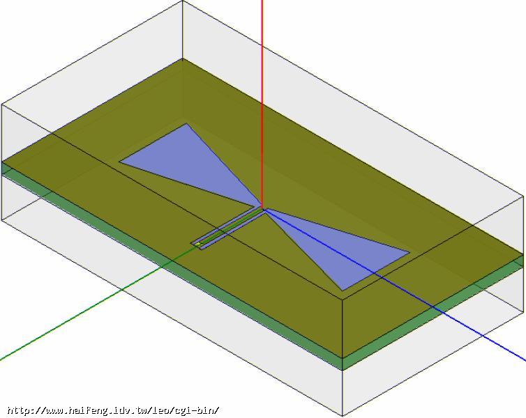
My question is about the size of the airbox. I saw in the HELP that the boundary should be located at least a quarter wavelength from the radiating source.Here is the example from the full book, CPW Fed Bowtie Antenna. I think everyone see it before.
In its discusstion of the airbox size, it uses 8Gz as frequence and get a 9.5mm spacing of airbox. While, the dimension of this example's structure is 0.6mm width of center conductor and 34mm*64mm of substrate plane. As in my CPW design, I have the same frequency within the example. And the center conductor width is 100μm, the length of transmission line is 1000μm=1mm, substrate's region is 1mm*2mm, which is far away from the theoretical airbox size of 9mm.
I run the optimetrics function in HFSS and use different height of airbox from 2300mm=2.3μm to 9000mm=9μm. There seems no difference at all. I am confused. Should I still stick to the 1/4 wave length restriction?
Thank you!
I'm new to HFSS and I have questions about the airbox. My understanding and questions are just as follows. Hope you can point out my fault and any discussion on the topic is welcomed.
As to my knowledge, the airbox is an artificial boundary that one set to separate the model structure with the outer perfect electric conductor(PEC). If there isn't an airbox, the structure will perform like inside a metal box and the electrical field will reflect when it touches the box, which not want to be seen in the simulation. So that's why we need a airbox that large enough to not infect the distribution of electric field. Also by defining a different sizes of airbox, we can decide the region that one need to solve the problem, which leads to the analysis time. The larger size of airbox, the longer time one needs. Is my understanding correct? Or you may have different opinions.
My question is about the size of the airbox. I saw in the HELP that the boundary should be located at least a quarter wavelength from the radiating source.Here is the example from the full book, CPW Fed Bowtie Antenna. I think everyone see it before.
In its discusstion of the airbox size, it uses 8Gz as frequence and get a 9.5mm spacing of airbox. While, the dimension of this example's structure is 0.6mm width of center conductor and 34mm*64mm of substrate plane. As in my CPW design, I have the same frequency within the example. And the center conductor width is 100μm, the length of transmission line is 1000μm=1mm, substrate's region is 1mm*2mm, which is far away from the theoretical airbox size of 9mm.
I run the optimetrics function in HFSS and use different height of airbox from 2300mm=2.3μm to 9000mm=9μm. There seems no difference at all. I am confused. Should I still stick to the 1/4 wave length restriction?
Thank you!