Continue to Site

Welcome to EDAboard.com

Welcome to our site! EDAboard.com is an international Electronics Discussion Forum focused on EDA software, circuits, schematics, books, theory, papers, asic, pld, 8051, DSP, Network, RF, Analog Design, PCB, Service Manuals... and a whole lot more! To participate you need to register. Registration is free. Click here to register now.

HF current transformet calculating

Status
Not open for further replies.

k.karel

Newbie level 6
Joined
Sep 17, 2009
Messages
11
Helped
0
Reputation
0
Reaction score
0
Trophy points
1,281
Activity points
1,366
Hello for all,
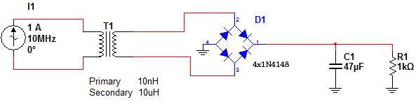
I have line with sin 10MHz and current 0 - 1A rms this signal go over current sense transformer (Iron powder toroid) primar winding (2 turn) have induction 10nH, sec. winding have 10uH, on secundar is diode Greatz bridge and C + load resistor. viz picture.
What will be voltage on C1?
Is possible use ferite core on 10MHz?
 

Dear buddy
Yeah it is possible.
The voltage of capacitor will be A dc voltage.(if your voltage can going your diodes in forward bias( upper than 0.6 volt for silicon diodes.)
 

Yes. It is possible to use ferrite core. You should try to keep B value as low as possible (increase the turns). You can calculate the sec side voltage by calculating (primary voltage*turn ratio )-diode drop. I thing it should be around 19V approx
 

I'm pretty sure rectifying the current into such a large C and small R will give you a very bad reading. If you want a DC output, rectify the signal into a low value resistor, then put that through a high impedance lowpass filter.
 

Status
Not open for further replies.

Similar threads

Part and Inventory Search

Welcome to EDABoard.com

Sponsor

Back
Top