Continue to Site

Welcome to EDAboard.com

Welcome to our site! EDAboard.com is an international Electronics Discussion Forum focused on EDA software, circuits, schematics, books, theory, papers, asic, pld, 8051, DSP, Network, RF, Analog Design, PCB, Service Manuals... and a whole lot more! To participate you need to register. Registration is free. Click here to register now.

Help with WDT, WDT resetting PIC

Status
Not open for further replies.

milan.rajik

Banned
Advanced Member level 5
Joined
Apr 1, 2013
Messages
2,524
Helped
540
Reputation
1,078
Reaction score
524
Trophy points
1,393
Visit site
Activity points
0
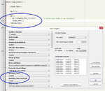
I am using PIC18F45K22 with 4 MHz external resonator. I am testing the project in both Proteus and hardware (EasyPIC 7). The code is mikroC PRO PIC code. Please see attached image. It shows my WDT configuration and the piece of code which is resetting WDT every 6 to 7 seconds.

The code of CLEAR_WDT() function is as below.

Code:
void CLEAR_WDT() {
      _asm clrwdt;
}

The keypad function is a non blocking function and so the program will be executing the do{ }while(!kp) loop. The program works fine in Proteus but in hardware WDT is resetting when it enters this do{...}while(!kp) loop.

I have used stop watch to check the time taken to execute this loop once and it is 160 us and WDT is cleared in this loop every 160 us but WDT is resetting the PIC.

If I disable WDT then program works fine in hardware.


Edit: Here is the latest hex file of the project. The proteus file of the project is attached here.

It works fine in Proteus. I have tested for 10 minutes in Proteus and WDT doesn't reset but in hardware WDT is resetting every 13 seconds.
 

Attachments

  • wdt prob.png
    wdt prob.png
    43.4 KB · Views: 165
  • hex.rar
    7 KB · Views: 87
Last edited:

Nothing to do with the problem but I ask why you are putting the watchdog reset in a function. With only one instruction it makes more sense to embed the _asm line directly into the program. As it is, you add unnecessary extra code to perform the call, return and possibly memory manipulation to reach the function.

If it is for clarity when reading the program, can't you '#define' it or even make it a macro.

Brian.
 

Earlier I was using _asm clrwdt piece code all over the program. Later with no specific reason I changed it to a function. Similar usage of WDT in a different project with same PIC18F45K22 works fine with same WDT settings but in this project it is resetting PIC in hardware.
 

Code:
void main() 
{
OPTION_REG = 0x0E; // put ur prescaler value here
asm CLRWDT; // Assembly command to reset WDT timer

code_enter(); //without clrwdt(); use your key function

while(1);


}
 

There is no OPTION_REG in PIC18F45K22.

you can use your respective controller register that was just example.sorry my mistake i didn't mention in my last post.

Code:
Watchdog Timer Enable bits:
;     WDTEN = OFF          Watch dog timer is always disabled. SWDTEN has no effect.
;     WDTEN = NOSLP        WDT is disabled in sleep, otherwise enabled. SWDTEN bit has no effect
;     WDTEN = SWON         WDT is controlled by SWDTEN bit of the WDTCON register
;     WDTEN = ON           WDT is always enabled. SWDTEN bit has no effect
;
;   Watchdog Timer Postscale Select bits:
;     WDTPS = 1            1:1
;     WDTPS = 2            1:2
;     WDTPS = 4            1:4
;     WDTPS = 8            1:8
;     WDTPS = 16           1:16
;     WDTPS = 32           1:32
;     WDTPS = 64           1:64
;     WDTPS = 128          1:128
;     WDTPS = 256          1:256
;     WDTPS = 512          1:512
;     WDTPS = 1024         1:1024
;     WDTPS = 2048         1:2048
;     WDTPS = 4096         1:4096
;     WDTPS = 8192         1:8192
;     WDTPS = 16384        1:16384
;     WDTPS = 32768        1:32768
 

That I have already done. Those are selected from the Project Settings menu in mikroC. See the image in first post.
 

Please see example for PIC18F45K22 from compiler example folder:

Code:
/*
 * Project name:
     WatchDog_Timer (Demonstration of the Watchdog Timer usage)
 * Copyright:
     (c) MikroElektronika, 2005-2008
 * Description:
     This code demonstrates how to embed Assembly language blocks
     and how to clear the Watchdog timer.
 * Test configuration:
     MCU:             PIC18F45K22
                      http://ww1.microchip.com/downloads/en/DeviceDoc/41412D.pdf
     Dev.Board:       EasyPIC7
                      http://www.mikroe.com/easypic/
     Oscillator:      HS-PLL, 32.00000 MHz
     Ext. Modules:    -
     SW:              mikroC PRO for PIC
                      http://www.mikroe.com/mikroc/pic/
 * NOTES:
     - Turn on Watchdog Timer in Edit Project window.
     - Turn on LEDs on PORTB switch SW3.2 (board specific).
*/

void main() {

  ANSELB = 0;        // Configure AN pins as digital
  asm CLRWDT;        // asm line, clear WatchDog Timer
  LATB  = 0x0F;      // Initialize PORTB
  TRISB = 0;         // Configure PORTB as output
  Delay_ms(300);     // Wait 0.3 seconds
  LATB  = 0xF0;      // Change PORTB value
 
  while (1)          // endless loop, WatchDog_Timer will reset PIC
    ;
}

with your settings WDT is configured to reset the PIC.sorry but I didn't get what you are trying to do with WDT in key function.
 

Dear ud23

It seems that you don't know how WDT works. Lets say that I set the WDT to reset every 2.3 sec then I have to clear wdt in the program at different places so that wdt doesn't reset the PIC. Only if the MCU hangs or stucks in a loop where wdt is not cleared then PIC will reset. With such a thing one can be sure that his system runs without problem. Even if it stucks then it resets and restarts and the system will be running all the time.

In my code the do{...}while(!kp) loop is used to read keypad and the do while loop is a blocking code and hence I am celaring wdt inside the loop so that wdt doesn't reset the PIC. If I don't clear wdt then wdt will reset PIC due to that do while loop. The loop is only called during setup. Once the password and mobile number for the system is setup then the program will not enter that do while loop. For after setup, keypad has to be used to re-enter setup mode.

Maybe it is bug of mikroC PRO PIC Compiler. I have even turned of optimization to make sure that wdt piece of code is not eliminated.
 

I have seen on other threads that people have had similar problems with MikroC so perhaps it is a compiler bug. It is purely a guess but maybe some errant compiler code is crashing your program and that causes the WDT reset rather than it being part of the code you have written. I gave up on that compiler a long time ago, does the newer version have a debug trace facility so you can back-tack to the instructions that executed at the time the reset ocurred?

Brian.
 
Thank you betwixt. I love mikroC Compiler. I have requested mikroE for support regarding the issue. I am waiting for their response. Maybe it is bug of Compiler and if yes I will wait till mikroE provides a fix.
 

Status
Not open for further replies.

Similar threads

Part and Inventory Search

Welcome to EDABoard.com

Sponsor

Back
Top