rafako
Newbie level 4
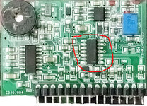
Greetings, I have a 1000W inverter, and I understand that it is not the latest in technology, but I want to repair it. The issue is with the SPWM module; it has a cross-linked processor, and its code has been erased. If someone could help me with more information about the processor and its program, it would be a solution not only for me but also for many people who use these models and do not have access to electricity in their villages, in the midst of the 21st century. It's incredible, isn't it? I am attaching a photo of the module. I hope for your assistance. Regards