Continue to Site

Welcome to EDAboard.com

Welcome to our site! EDAboard.com is an international Electronics Discussion Forum focused on EDA software, circuits, schematics, books, theory, papers, asic, pld, 8051, DSP, Network, RF, Analog Design, PCB, Service Manuals... and a whole lot more! To participate you need to register. Registration is free. Click here to register now.

Help with 2-switch forward converter

Status
Not open for further replies.

binaryninja

Member level 3
Joined
Nov 11, 2010
Messages
65
Helped
2
Reputation
4
Reaction score
2
Trophy points
1,288
Activity points
1,945
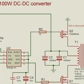
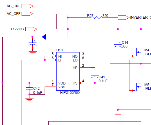
Hi all, I had posted a long time with a project for a 12V to 110VAC inverter. The front end that creates the high voltage needed by the H-bridge is a 2-switch forward converter. It takes in 12V and produces 155V, and it works up until it breaks. Looking at the schematic, C14 (Cin) blows and then U10 will burn up, also M4 appeared to fail at the same time. I'm trying to figure out why this is happening and what needs to be done to correct it. Any help will be greatly appreciated for I am swamped and do not have enough experience with power supplies. Thanks!

I realize you may need more info to make an accurate assessment. Please just ask me.
 

Attachments

  • 2-switch fwd converter.png
    2-switch fwd converter.png
    77.4 KB · Views: 194
Last edited:

Are you sure that the failures happen in that order? How fast does the failure occur after startup? Does it only happen with a large load applied? Do any components get hot gradually leading up to the failure?
 
Hi, thanks for responding. I am about 98% sure that the input capacitor blew first. Could this be caused by ripple current? After, Cin blew, I noticed U10 had a pin size hole near the VCC pin. Next I replaced U10, left off Cin, and M4 was not operating anymore. So I don't know if it happened all at once or if it was a cascading effect.

The failure occured about 2-3 seconds after applying a 55W bulb as the load. Previously, a 25W bulb was working fine. Could it have been in rush current? Or would this have happened sooner?

I don't know how hot things got before the failure. I'm looking for any ideas as to why this would have happened.
 

Boosting and glitches in power rail, battery lead can act as boosting coil. C14 is of very low value. Low esr capcitors in paralell of around 10,000uF should be used. ETD44 core can support many hundred watts load.
 
ETD44 core can support many hundred watts load.
The supply is designed and intended to supply 200W.

Low esr capcitors in paralell of around 10,000uF should be used.
I agree with low ESR and the value should be increased, but 10,000uF seems excessive. How do you validate this value? From calculations for Cin, I get anywhere from 80uF to 330uF.
 

I meet such a problem before, i haven't solved , i will use the way to have a try .
 

From calculations for Cin, I get anywhere from 80uF to 330uF.
How did you calculate? I see too scenarios:
- the input source is a low impedance battery, then these tiny capacitors are about to be meaningless
- the battery is not so low impedance or there is a considerable cable resistance and inductance between battery and inverter. Then the capacitor has to handle at least 20 A peak currents. Do you think it's prepeared to?
 
In my view ....Please check the load as you are geeting more tan 60 v drop and second thing I will recommand you to use 220E resistance or some thing in that order between Gate of MOSFET and HPC chip

Good Luck
 

How did you calculate?
I used a couple of different equations from app notes or online. The easiest one that I remember is Cin = (1uF/W)(Pin), and depending on efficiency Pin changes. If you know an equation or capacitor value that is best for my design please point me in the right direction.

Then the capacitor has to handle at least 20 A peak currents. Do you think it's prepeared to?
Probably not, how would I spec a capacitor that would handle 20A peak currents?

So, I believe the consensus is that my input capacitor should be increased to a much larger value with maybe a couple in parallel.
 

42_1320999004.png

Use rectifier and filter capacitor to avoid reseting ics when strong glitches are present on power lines. Saturation of core due to wrong switching will be avoided. This is another cause of circuit blowups.
 
Thanks for the help Alertlinks.

Saturation of core due to wrong switching will be avoided.

Could you please explain how the addition of the rectifier and capacitor help with this?
 

When 55 Watts load was connected,it was not 55 Watts. The cold filament resistance is lower and initial power surge may be four times higher for few milliseconds. A current sense circuit copes with this situation by reducing pulse width even if voltage go down. In your schematics you are using two resistors R38 and R83 in parallel equels to .01 ohm. That means 100 ampers through these resistors will produce 1 volt. At that poin LT1245 will try to keep current below 100Amps because its current limiting function activates above 1V equals 1200 watts load. Two .1 ohm resitors will limit load above 240 watts
When there is overload on power line 12V, it may reduce to 6V due to resistance or loose connection. LT1245 has a "low voltage lockout" function that means it stops operating below around 7.5V but then starts again near 8.5V.(when oscillation stops,current is lowered, voltage rises on power line, oscilation starts again) Random oscillations generated causes further overloading and saturation of core. Diode charges capactor to peak and when volt becomes less for a short time(glitch), capacitor provide voltage required( same as filter capacitor does in ac rectification). This can also assist filter capacitor on power rail providing more filteration to control circuit.
Sensing output current acts more rapidly, it is ignored in your schematic.
 
Right, I had to dramatically decrease the current sense resistor values, and even added one in parallel (hence R83) to deal with the large amount of current. It does exactly that, limits the switching current to 100A. Previously, I had a .2 Ohm current sense resistor but the output voltage drastically dropped, with just a 10W load.
Sensing output current acts more rapidly, it is ignored in your schematic.
Every example I looked at senses current on the primary side switch. If one were to implement current sensing on the output, does that eliminate the current sensing on the primary side? If so, that means that I would be able to get cheaper current sense resistors at a larger resistance.

I understand now why you suggested what you did, thanks.
 

Current sense for both input and output is better. The output filter capacitor delivers current first then load is transfered to input. So sensing current after filter capacitor can give instant response. Primary side sensing should be sufficient if properly configured. It seems your layout problem that such low value resistance is needed, maybe there is more resistance in wiring. You should go for short circuit protection.
 
Last edited:
Status
Not open for further replies.

Similar threads

Part and Inventory Search

Welcome to EDABoard.com

Sponsor

Back
Top