Continue to Site

Welcome to EDAboard.com

Welcome to our site! EDAboard.com is an international Electronics Discussion Forum focused on EDA software, circuits, schematics, books, theory, papers, asic, pld, 8051, DSP, Network, RF, Analog Design, PCB, Service Manuals... and a whole lot more! To participate you need to register. Registration is free. Click here to register now.

[SOLVED] Help with 100W Guitar Amp

Status
Not open for further replies.

DA-Drummer

Newbie level 5
Joined
Sep 20, 2013
Messages
9
Helped
0
Reputation
0
Reaction score
0
Trophy points
1
Activity points
75
Hello everybody

I have some trouble with a 100W guitar amp i am building.

This is the Guitar Amp: **broken link removed**

This is my PowerAmp lay out:
poweramp2_zps38dc82dd.jpg


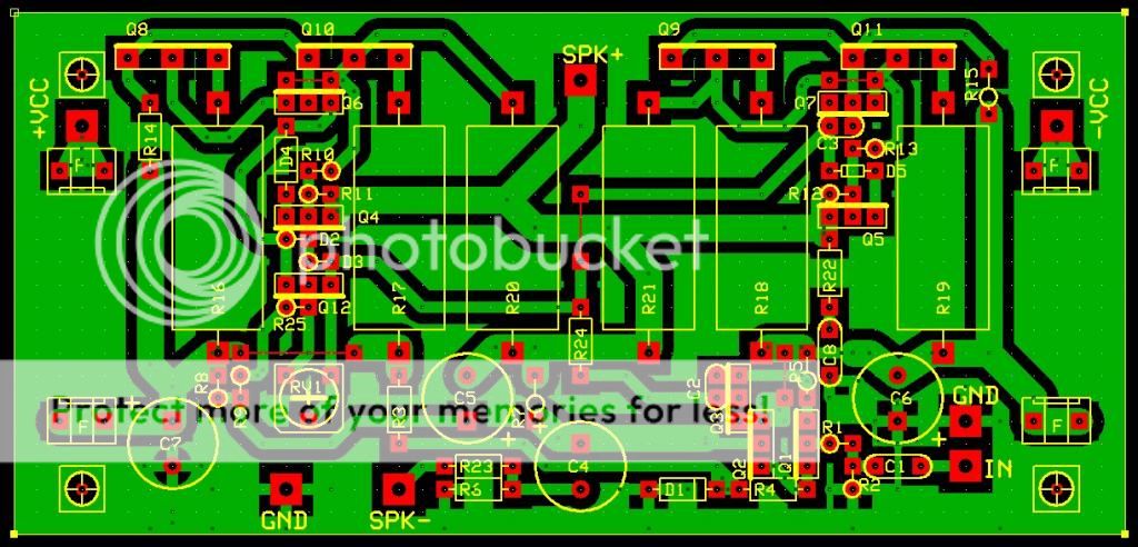
And for the guys with ExpressPCB: https://www.mediafire.com/download/envpqboftm9c4v2/PowerAmp2.pcb

The problem is that te Tip36 and Tip35 are getting hot(very hot), even if the input is on ground.
and Q8 and Q9 get hotter then the other to(but that is because i didnt put them yet on a heat sink, so there may be some thermal runaway).

The power supply works fine.
And the voltage over R16 and R18 are 0.08V to 0.2V (or even more) depending on the bias of Q12.
They dont get hot if turn my potentiometer al the way down, but i don't think it's design to turn all the way down.

And i attatched a speaker on the output, and nothing is coming out of it, no noise, cracking or guitar sound.

Please help me.

Cheers DA-Drummer
 

do you placed tip35 & 36 in their proper location.? i think npn & pnp transistors are reversed. also check the transistors are ok or not by dmm diode test position test

- - - Updated - - -

place your assembled pcb photo
 

Did you follow the "Testing" instructions at the bottom of the page? In particular:

Connect a multimeter between the collectors of Q10 and Q11 - you are measuring the voltage drop across the two 0.22 ohm resistors (R20 and R21). The desired quiescent current is 25mA, so the voltage you measure across the resistors should be set to 11mV +/-2mV. The setting is not overly critical, but at lower currents, there is less dissipation in the output transistors. Current is approximately 2.2mA / mV, so 10mV (for example) will be 22mA.

Keith
 
And the voltage over R16 and R18 are 0.08V to 0.2V (or even more) depending on the bias of Q12.
Did you understand the bias current setup instructions? 25 mA suggested for a guitar amp would drop only 5.5 millivolts across a 0.22 ohm resistor. Operating output transistors without heatsink shouldn't be considered as serious idea, even for test.

If the amplifier doesn't work at all, you'll want to check the operation point of all transistors, e.g. by measuring the voltage of all circuit nodes against ground. Or hook up a signal generator to the input and trace the AC voltage with an oscilloscop.
 
The Tip's are placed in proper location, and yes i followed the insturction on the page.
And i have to do the bias set up(am i going to do that right now).
And i don't have all that test equipement at home.
 

I think the bias current thing worked very well, the Amp is not getting hot anymore, but still no sound.
And i connected te +VE & -VE right and the supply voltage is +35V and -35V.
A friend of mine has a scope at home, so maybe i am going to test that at his place, or maybe school.

Thank you for all te responses

- - - Updated - - -

Now i noticed that Q3 is getting hot. maybe that is the problem of not getting sound. am going to check the pcb lay out once again(10th time or so)
 

Q3 should not get hot. Did you orient it correctly? Is it shorted?
 

i think the problem is q3, because it get's hot, and when i measured in that area, the speaker made some "ticking" noise everytime i maked contact with the multimeter.
But i dont think it's the lay out that fails, because i checked the area round Q3 a dozen times. so maybe Q3 is broken.

Maybe you guys have some suggestions, but i will measure some more an maybe replace Q3.
 

Maximum power dissipation of Q3 would be about 220 mW, observed with zero output voltage and +/- 35 V supply. It won't be higher when Q3 is broken.

As said, the circuit problems would be usually narrowed down by measuring all node voltages.
 

i solved a problem and i got another one :(

When is was testing R8 bruned out, so i measured in that spot, and turned out R9 wasn't 4.7K but 47 Ohm.
So i replaced R8 and R9 with the correct values, but now when i turn it on. the TIP's are getting very hot, and the two 22Ohm/5W resistors that are in the fuse holders are getting very hot too.

So i thought maybe its the bias settings, so i adjusted the bias. But i won't get lower then 0.4V, and it has to be around 6mV.

So does anyone have suggestions?
 

no one had suggestions??

- - - Updated - - -

I have got some more information for you guys

Supply volage drops to +11V and -11V
And if i remove Q1 and Q2, the bias settings are correct, and the amp won't get hot.
 

And again i have some new information.

The Basis -> Emitter voltage of the Tip's are 0,5V
The whole circuit is tacking 0.9A
And through R20 and R21 goes 0.9A
And over the 15V Zener diode is 150mV

I asked my brother(3th year electrical engineering at TU Delft) and he doesn't know to problem.

So do you guys have any suggestions?
 

Supply voltage is only +11V, -11V at 0.9A current consumption so replace your power supply.
 

Supply voltage is only +11V, -11V at 0.9A current consumption so replace your power supply.
Respectively adjust the bias circuit for specified current.
 

Once you have the inadequate supply problem sorted out and the idling current is still out of control, try this: Temporary bridge out D2 or D3. If the idle current drops drastically and the devices don't overheat any more, then you may have some problem in the Vbe spreader function around Q12.
 

Supply voltage is only +11V, -11V at 0.9A current consumption so replace your power supply.
Power supply is correct, just the supply rails on the pcb are around 11V

Respectively adjust the bias circuit for specified current.
For some reason i can't re-adjust the bias settings(and yes my potentiometer is working correctly)
 

Status
Not open for further replies.

Similar threads

Part and Inventory Search

Welcome to EDABoard.com

Sponsor

Back
Top