FiFtHeLeMeNt
Newbie level 3

- Joined
- Jan 17, 2013
- Messages
- 3
- Helped
- 0
- Reputation
- 0
- Reaction score
- 0
- Trophy points
- 1,281
- Activity points
- 1,310
Hi Guys ")
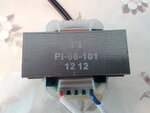
Can anyone help to identify the output voltage of this transformer ?
It belongs to an andis hair clipper charger. its input voltage is 110v which I connected it to 220v and it got burned. now I need to replace it.
As you can see in the picture its code is PI-66-101 12 12. I thought it may be some type of coding which someone knows about it.
I have tried to contact manufacturer for 1 month, but there has been no help
I would appreciate if someone can help me.
Regards