Continue to Site

Welcome to EDAboard.com

Welcome to our site! EDAboard.com is an international Electronics Discussion Forum focused on EDA software, circuits, schematics, books, theory, papers, asic, pld, 8051, DSP, Network, RF, Analog Design, PCB, Service Manuals... and a whole lot more! To participate you need to register. Registration is free. Click here to register now.

(Help!) PSpice Design of Active Bandpass Filter Giving Odd Bode Plot

Status
Not open for further replies.

spiralup

Newbie level 2
Newbie level 2
Joined
Dec 1, 2014
Messages
2
Helped
0
Reputation
0
Reaction score
0
Trophy points
1
Visit site
Activity points
22
I am trying to design an active band-pass filter with center frequency of 6.8MHz, bandwidth of 17kHz, and a gain of 14.
I used these values (14= (Rf/R1) +1)to select the resistors for the gain. I chose Rf to be 1300 and R1 to be 100.
Since BW = R/L, I chose R to be 170 and L to be 0.01. C was found to be 2.16E-12 (this is a bit suspicious to me, but it is what I have repeatedly calculated from center frequency = (R/2L) + (sqrt(R^2C^2+4LC)/2LC)).
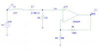


I used a VAC source. The AC analysis from 10k to 20M yielded this linear plot:


and this decade plot:


For the linear plot, shouldn't taking 20*log[Vout/Vsource] yield the bode plot?

Both are giving an odd spike in the Vout around 1 MHz. It needs to be 6.8 MHz though. Changing the value of C did move the spike closer to 6.8MHz, but 2.16E-12 was my calculated value. I am not sure what to try next.
 

This isn't actually an active bandpass, rather a passive LC filter followed by a gain stage, which simplifies calculations.

Obviously you got the resonance frequency wrong, but that's no the only design problem. You should face the fact that it's almost impossible to achieve the intended Q of 400 for 6.8 MHz filter with technically available inductors.
 

Thanks for the reply!

That makes sense, since I was instructed to connect the output of a passive filter to a non-inverting op-amp to get this far. I was told that would yield an active bandpass (active= op-amp is an active element, bandpass= only certain frequencies are allowed to pass).

This is a project for school that will only be using the ideal conditions in the simulator. I have to find the RLC values given the center frequency of 6.8 MHz (and the bandwidth and gain), unless I can argue that the simulator cannot accomplish that. I am new at this, so what value of Q would be "reasonable"? I know that Q describes how underdamped the oscillation is.
 

Try this page ( there are lot ..)
https://www.wa4dsy.com/robot/bandpass-filter-calc

- - - Updated - - -

There are some standard Active Filter approximations.One example and simulation results.
active_filter.png
Active_filter.png
 

Thanks for the reply!
That makes sense, since I was instructed to connect the output of a passive filter to a non-inverting op-amp to get this far. I was told that would yield an active bandpass (active= op-amp is an active element, bandpass= only certain frequencies are allowed to pass).
This is a project for school that will only be using the ideal conditions in the simulator. I have to find the RLC values given the center frequency of 6.8 MHz (and the bandwidth and gain), unless I can argue that the simulator cannot accomplish that. I am new at this, so what value of Q would be "reasonable"? I know that Q describes how underdamped the oscillation is.

Spiralup - it is not clear to me what you need. Therefore, my questions:
1.) Do you intend to design on a paper only (simulation) or also hardware?
2.) Are you required to design a PASSIVE filter only?
3.) Are you allowed to select any filter topology?
4.) Are the filter parameters fixed? (6.8 MHz; 17 kHz) resulting in a quality factor Q=400 ?
 

Status
Not open for further replies.

Similar threads

Part and Inventory Search

Welcome to EDABoard.com

Sponsor

Back
Top