Continue to Site

Welcome to EDAboard.com

Welcome to our site! EDAboard.com is an international Electronics Discussion Forum focused on EDA software, circuits, schematics, books, theory, papers, asic, pld, 8051, DSP, Network, RF, Analog Design, PCB, Service Manuals... and a whole lot more! To participate you need to register. Registration is free. Click here to register now.

Help PIC 16F877 ADC... thnx

Status
Not open for further replies.

_ciel_

Newbie level 4
Joined
Aug 4, 2011
Messages
6
Helped
0
Reputation
0
Reaction score
0
Trophy points
1,281
Activity points
1,333
hi guys, i currently a newbie here and a newbie in programming.
i only have micro studio. proton ide and isis as my means of programming and simulation pic ic's.
can someone teach me the basic in programming an ADC in pic 16f877?
i'm not well verse in assembly and c language that why i cannot relate with other sample program here in the net...
i'm currently working on a project using this ic and a fsr, i will be implementing the force sensing of the fsr to a pick and place robotic arm...
 

Hi,
As far as I know PROTON is for BASIC, not C. So, with PROTON, you have to program in BASIC, not C.

You should go through the datasheet first. This will give you a good idea. Then, you can proceed.

Datasheet for 16F877: ww1.microchip.com/downloads/en/devicedoc/30292c.pdf
Datasheet for 16F877A: ww1.microchip.com/downloads/en/devicedoc/39582b.pdf

Hope this helps.
Tahmid.
 

hi,
from the datasheet we get the register description of the pic 16f877.
if we get the working and uses of registers. we can program using 'c'.
 

Yes sir its for basic, i'm not too familiar in c language and i find quite to complicated to understand for beginners like me.. And all the source codes are in assembly and c language so im quite confused with it...
 

hi,
the c programming is easy for a big project. you want only the 'ADC reading' it can be coded using assembly language. then where you can see the result? a LCD or 7 segment display is needed. for coding with assembly you need to study all the instruction set. but in c coding only think about the registers that is the difference.
 

I can display the output in LED's first to check, the output will be the equivalent response of the Force sensing resistor that i will mount on the gripper of a pick and place robot arm... That's why i need the ADC reading... Do you have a sample of the ADC program that will display its output in LEDs, for me to have a basis. Thanks for the help
 

If you use mikroC, it has internal library functions to help you with ADC reading. One example could be as simple as:
Code:
unsigned int temp_res;

void main() {
  ANSEL  = 0x04;              // Configure AN2 pin as analog
  ANSELH = 0;                 // Configure other AN pins as digital I/O
  C1ON_bit = 0;               // Disable comparators
  C2ON_bit = 0;
  
  TRISA  = 0xFF;              // PORTA is input
  TRISC  = 0;                 // PORTC is output
  TRISB  = 0;                 // PORTB is output

  do {
    temp_res = ADC_Read(2);   // Get 10-bit results of AD conversion
    PORTB = temp_res;         // Send lower 8 bits to PORTB
    PORTC = temp_res >> 8;    // Send 2 most significant bits to RC1, RC0
  } while(1);
}

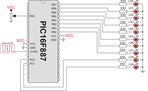
Hardware connection:
43_1312572725.png


Equivalent code for mikroBASIC:
Code:
program ADC_on_LEDs
dim temp_res as word

main:
  ANSEL  = 0x04                 ' Configure AN2 pin as analog
  ANSELH = 0                    ' Configure other AN pins as digital I/O
  C1ON_bit = 0                  ' Disable comparators
  C2ON_bit = 0

  TRISA  = 0xFF                 ' PORTA is input
  TRISB  = 0                    ' PORTB is output
  TRISC  = 0                    ' PORTC is output

  while (TRUE)
    temp_res = ADC_Read(2)      ' Get 10-bit results of AD conversion
    PORTB = temp_res            ' Send lower 8 bits to PORTB
    PORTC = word(temp_res >> 8) ' Send 2 most significant bits to RC1, RC0
  wend
end.

These are just sample codes and need to be altered and more settings configured in your final code.

Hope this helps.
Tahmid.
 

thank you very much Tahmid. this is a big help. i'll try it later i'm heading of school right now. thanks again :-D
 

i've made this code based on some of the ideas that i've read can you please evaluate in its written in micro studio


Define ADC_BITS 8
Define ADC_SAMPLEUS 50
'Define ADC_CLOCK 3
ADCON0 = %11000000
ADCON1 = %00000000
ADRESL = %00000001
ADRESH = %00000000


abc Var Byte


TRISA = %11111111
TRISD = %00000000
Pause 500

mainloop:
ADCIN 0, abc
PORTD = abc


Pause 100

Goto mainloop

End

my problem now it how can i adjust the resolution of the adc reading so that i can the 8bits pattern
00000000
00000001
00000010
00000011 and so on...
my circuit only has ten resolution based on the pot i've been using
do i need to do something else or can this actually be use to have an output pattern of the 8 bits and my pot only limits it?
 

i've evaluated my work and i does have 00000001 output when the voltage across the resistor is 0.0195v it also increments when you add 0.0915 v... thanks for the help... i'll post again if i encounter some problems...
 

hi,
i need some help:-D
i try this and don t work... in microc i have one eror: C1ON_bit = 0; // Disable comparators
C2ON_bit = 0;
i erase this and the program work but the simulation in proteus doesn t work , all the leds are on!
can anybody help me?
thanks!
 

Which microcontroller are you using? The above codes are for 16F887. For 16F877A, you have to change it since 16F877A doesn't have any ANSEL register or C1ON or C2ON bits.

EDIT: AN2 is multiplexed to the comparator. My mistake. So, you need to disable comparator.

Hope this helps.
Tahmid.
 
Last edited:

I reallu want to convert a square wave in digital bit with pic 16F877, and do not know how.
I tried the above example with pic 16f887, I deleted C1ON and C2ON ,the buiding was good but when I run a simulation program in Proteus all the LEDs are on, I move the cursor and nothing happens, the leds are on.
the program in microc is:

Code C - [expand]
1
2
3
4
5
6
7
8
9
10
11
12
13
14
15
16
17
unsigned int temp_res;
 
void main() {
  ANSEL  = 0x04;              // Configure AN2 pin as analog
  ANSELH = 0;                 // Configure other AN pins as digital I/O
 
 
  TRISA  = 0xFF;              // PORTA is input
  TRISC  = 0;                 // PORTC is output
  TRISB  = 0;                 // PORTB is output
 
  do {
    temp_res = ADC_Read(2);   // Get 10-bit results of AD conversion
    PORTB = temp_res;         // Send lower 8 bits to PORTB
    PORTC = temp_res >> 8;    // Send 2 most significant bits to RC1, RC0
  } while(1);
}


the simulation scheme in proteus :
**broken link removed**

sorry for my bad english but it is not my native language :D
thanks for help!
 
Last edited by a moderator:

For the above code that you tried on 16F887, C1ON and C2ON bits cause problems? Are you sure?
After ANSEL, type in these 2 lines:
Code:
CM1CON0 = 0x80;
CM2CON0 = 0x80;

They should disable the comparator.

Hope this helps.
Tahmid.
 

it doesn t work,all the leds are on ...
adc.JPG
 

i've made an archive with DSN and HEX file
**broken link removed**
 

I think you should check the archive. I've downloaded it and extracted it. But there are no files inside and the file size is shown as 67 bytes. Maybe there was some problem in compressing or uploading.
 

sorry,
**broken link removed**
 

Status
Not open for further replies.

Similar threads

Part and Inventory Search

Welcome to EDABoard.com

Sponsor

Back
Top