wizpic
Advanced Member level 3

- Joined
- May 23, 2004
- Messages
- 792
- Helped
- 108
- Reputation
- 216
- Reaction score
- 72
- Trophy points
- 1,308
- Location
- London
- Activity points
- 6,404
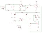
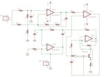
I have this circuit (Battery ampere hour monitor)and have a basic idea of how it works but would like to understand it a bit better. The principle of the circuit is that it's a bidirectional current flow monitor a 0-60mv signal comes in through X1 from 60amp shunt and it gets fed and amplified through IC1A then IC2A,B converts the signal to a positive value if the current is reversed. The part I'm un-sure of what is the purpose of R7,C2,D1,T1 and R10 does I presume it as something to do in converting the signal from a negative into a positive signal when the current flow is reversed ? . The rectified signal get's fed into IC1B. The output has a range of 0-1.8volts with 0-30amps current draw
Could someone please clarify this for me
Could someone please clarify this for me


