Ogu Reginald
Full Member level 6

- Joined
- Oct 7, 2011
- Messages
- 369
- Helped
- 47
- Reputation
- 94
- Reaction score
- 46
- Trophy points
- 1,308
- Location
- Nigeria
- Activity points
- 3,391
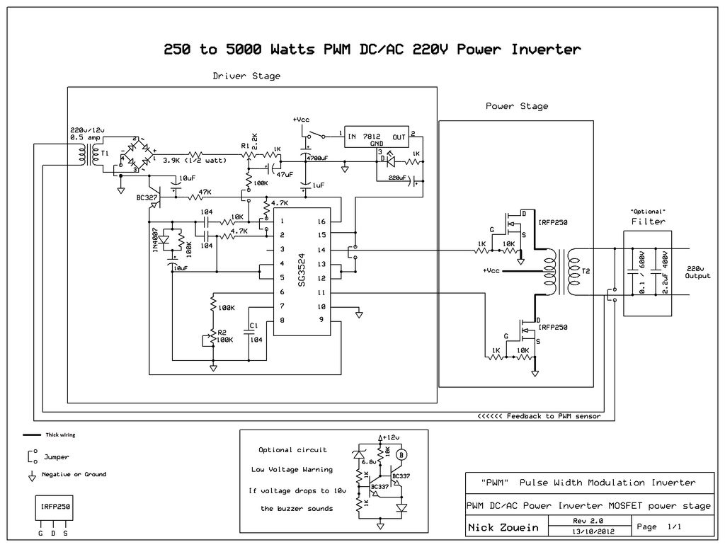
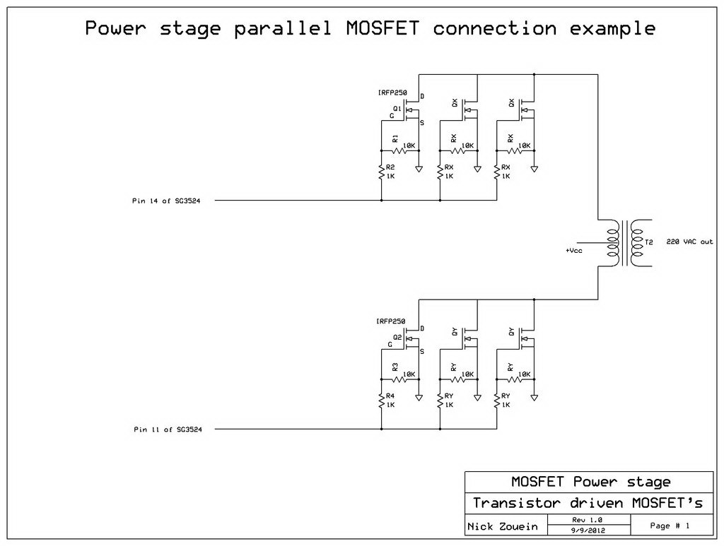
I have 2kVA inverter that I just built. During testing I just connected a 100watt bulb and it was working for about 10minutes but when i connected a 150watt fan to it , the bank of MOSFET got burnt.
Since then I have replaced the MOSFETs and connected no load to the Inverter output but at switch ON the MOSFETs still got burnt.
At no load should the inverter draw current from the battery to the extent that it can burn the MOSFETs?
Please can someone help me and tell me the possible cause of the problem.