Continue to Site

Welcome to EDAboard.com

Welcome to our site! EDAboard.com is an international Electronics Discussion Forum focused on EDA software, circuits, schematics, books, theory, papers, asic, pld, 8051, DSP, Network, RF, Analog Design, PCB, Service Manuals... and a whole lot more! To participate you need to register. Registration is free. Click here to register now.

Help needed in analyzing the combination of a Resistor and a capacitor in a Schematic

Status
Not open for further replies.

Qube

Member level 5
Joined
Nov 10, 2010
Messages
80
Helped
7
Reputation
14
Reaction score
7
Trophy points
1,288
Activity points
1,896
Help needed in analyzing the combination of a Resistor and a capacitor in a Schematic..?
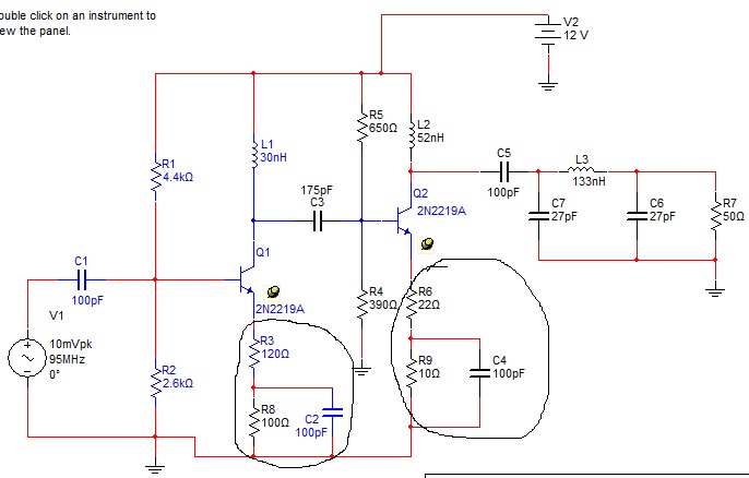
In this below schematic u can see two circuit marks,which points out a bypass cap in parallel with a resistor and also a resistor above this parallel cap/resistor..

46_1292824802.jpg


Please explain,
wat are it's functions..?
wat is it advantages..?
and wat is it disadvantages..?
And finally do u think that type of configuration is worth in this circuit.....

And i think the total resistance value can be determined at the Transistor's emitter by adding the the resistors value which are in series..Am i right????

Thank u
 

Adding some resistance such as R3 and R6 allows you to control the gain. There should be plenty of examples on the net, such as

Keith.
 

these are use for a stability and bypass capacitor use to pass ac signal
 

I think, the purpose of the components should be explained in more detail:
1.) R3 and R6 provide negative feedback for the signals to be amplified. This gives better linearity and increases the input impedance. At the same time the gain is decreased (see contribution from KEITH), but that's the normal price to be paid for better linearity.
2.) (R3+R8) and (R6+R9) provide negative feedback for DC (and very low frequencies) only. This stabilizes the operating point against tolerances and temperature deviations.

---------- Post added at 15:01 ---------- Previous post was at 14:18 ----------

*As far as the last question is concerned:
And i think the total resistance value can be determined at the Transistor's emitter by adding the the resistors value which are in series..Am i right????

The answer is: It depends. For dc feedback purposes both R's act in series. However, for calculating the corner frequency of the feedback high pass (very low frequecies: much feedback/lower gain; higher frequecies: less feedback/higher gain) both resistors have to be considered in parallel.

*One remark to sunny1986's "lapidar" statement "use for stability":
Negative feedback always has two consequences: It enlarges dc operating point stability and - at the same time - it lowers system stability (poorer stability margin) against self-excitement.
 
Last edited:
I tend to think of the non-decoupled emitter resistor as simply an addition to the AC impedance of the emitter when calculating the gain.

Keith
 

I tend to think of the non-decoupled emitter resistor as simply an addition to the AC impedance of the emitter when calculating the gain.

Keith

Sorry Keith, I don't understand the meaning of "addition to the AC impedance of the emitter when calculating the gain".
Don't you agree that R3 resp. R6 provide negative feedback thereby reducing the gain?

Example: gain of 1st stage is A=g*Xc/(1+g*R3)
for frequencies above the corner frequency of the emitter highpass
and with Xc=effective collector impedance (including Rin of 2nd stage).
 

Sorry Keith, I don't understand the meaning of "addition to the AC impedance of the emitter when calculating the gain".
Don't you agree that R3 resp. R6 provide negative feedback thereby reducing the gain?

Oh, yes, I agree that the effect R3/R6 is to reduce the gain. I would calculate the gain as Xc/(re+R3) where re is 25mV/Ie at room temperature. I think it gives the same result, just viewed in a different way.

Keith.
 

As was stated above, R3 and R6 provide negative feedback (long time ago was named emitter degeneration). This approach is common used in low signal wideband amplifiers for stabilization. Generally the value of these resistors shouldn't be greater than 10 ohms.
 

1.) Keith: OK, now I see what you mean. Of course, your formula is identical to mine for 1/g=re.


2.) vfone: "This approach is common used in low signal wideband amplifiers for stabilization".

I think, "stabilization" is a term which could be misunderstood without any explanation. Which parameter is stabilized?
(Answer: The dc operating point and the ac gain value against tolerances - but NOT the whole circuit against oscillation!)
 

Status
Not open for further replies.

Part and Inventory Search

Welcome to EDABoard.com

Sponsor

Back
Top