amdc
Junior Member level 3
microstrip filter
Hello All.
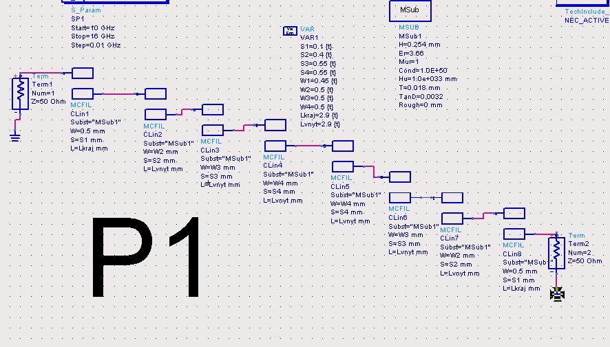
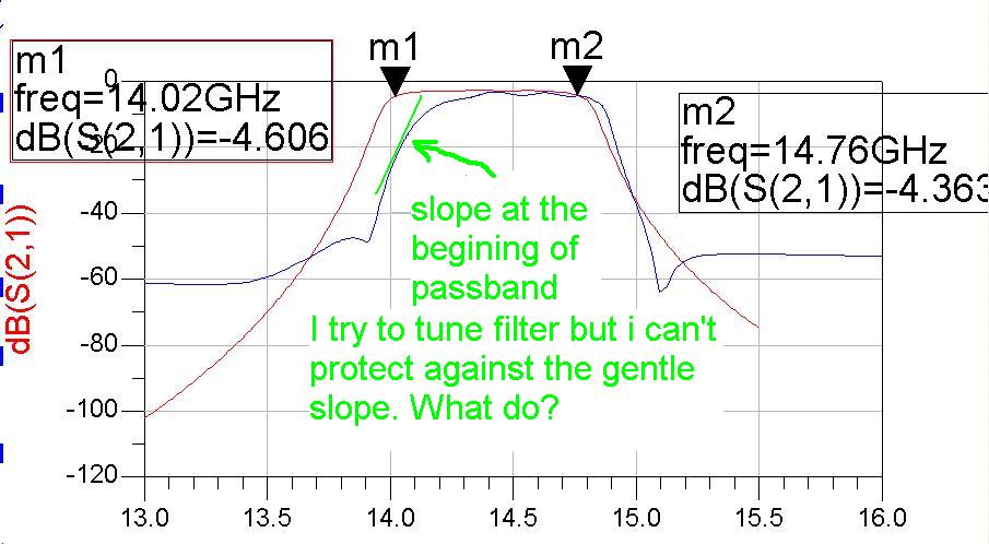
I design the microstrip coupled line filter with help Microwave Engineering Pozar. Parameters of the filter was calculated for 0.8Ghz passband with central frequency 14.4 Ghz.
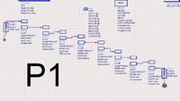
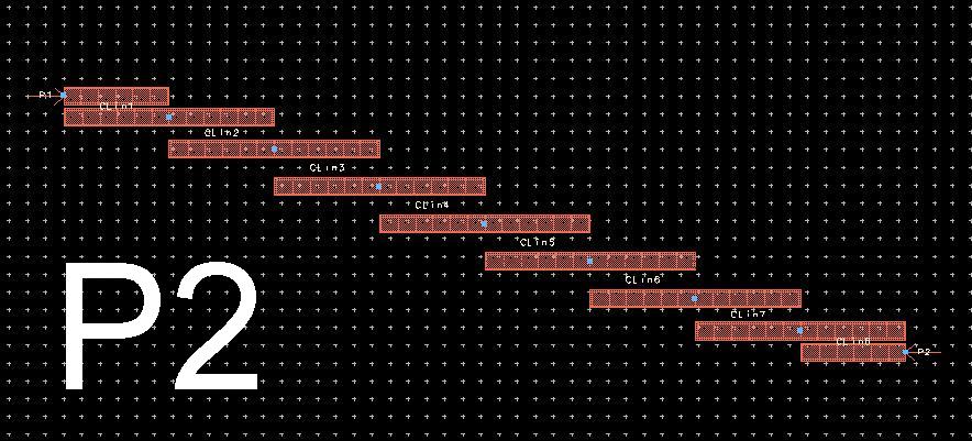
After i modeled it in the schematic and layout (It's shown on the pictures P1 and P2). And results was very different (see last picture)

I don't understand the slope at the begining of passband, I tune my scheme W, S, L of the filter but gentle slope is present
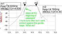
Could you explain what is happen and help me to improve results. THANKS BEFORE ! ! ! ! May be I have a mistake in electromagnetic simulation... How I do have to simulate my scheme in layout?
Hello All.
I design the microstrip coupled line filter with help Microwave Engineering Pozar. Parameters of the filter was calculated for 0.8Ghz passband with central frequency 14.4 Ghz.
After i modeled it in the schematic and layout (It's shown on the pictures P1 and P2). And results was very different (see last picture)
I don't understand the slope at the begining of passband, I tune my scheme W, S, L of the filter but gentle slope is present
Could you explain what is happen and help me to improve results. THANKS BEFORE ! ! ! ! May be I have a mistake in electromagnetic simulation... How I do have to simulate my scheme in layout?