xibalban
Newbie level 5

- Joined
- Apr 12, 2013
- Messages
- 8
- Helped
- 0
- Reputation
- 0
- Reaction score
- 0
- Trophy points
- 1,281
- Activity points
- 1,369
Hello fellas,
This is my first post, and my first electronic project endeavour. Let me put my project details as follows:
The Project
I have a Maruti Gypsy, an Indian version of Suzuki Samurai, with a fabric hood. I would like to install a music system on this vehicle:
An AM (Shortwave/Mediumwave) tuner
An MP3 player
Say, a 10 W + 10 W rms two speaker system
Why build a project, why not buy it?
Firstly, theft is an issue. My vehicle is always parked in the open, and anyone could unzip/un-button the soft fabric hood and lay a dirty hand on the system. Hence, I need to keep it concealed and discreet.
It is difficult to lay hands on an AM receiver anymore, with most systems preferring FM instead. Besides, these systems are a tad too expensive and come with redundant features like CD player, equaliser, remote, etc.
I wish to build the system out of salvaged parts, most of which I have access to.
Lastly, for the pride that I could gain from being able to build a novel music system customised to my vehicle's need.
What do I have in mind?
I have a LA4445 (**broken link removed**) salvaged out from an old tape-deck.
I also have a TA2003P (http://pdf1.alldatasheet.com/datashe...A/TA2003P.html)
I would assemble the circuit on a general purpose PCB and fix it under the bonnet; I have located a suitable spot near the battery to bolt the PCB through the heat-sink screw-holes.
...and I have the following plan in mind:
To feed the output from my cellphone (HTC Legend) through its 3.5 mm stereo jack to the stereo inputs of LA4445 based amplifier. My cellphone also works as FM radio, just in case.
To feed the output from TA2003P to the above cited amplifier using a toggle switch, placed suitably on the dashboard.
To embed a sliding-type potentiometer somewhere along/attached-with the 3.5 mm input cable to act as volume controller.
A common power on/off switch.

So, where do I seek help?
I request feedback on my design/block-diagram, please.
Which is the best way to regulate 12 V from car battery to 3.3 V rated for the TA2003P?
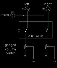
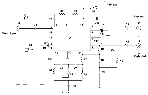
How do I feed mono output from the AM radio section to stereo inputs of amplifier section?
What is the best way to design the radio-antenna or ferrite coil, etc?
Anything else that I need to consider?
I thank you all for reading through this post. Cheers!!
This is my first post, and my first electronic project endeavour. Let me put my project details as follows:
The Project
I have a Maruti Gypsy, an Indian version of Suzuki Samurai, with a fabric hood. I would like to install a music system on this vehicle:
An AM (Shortwave/Mediumwave) tuner
An MP3 player
Say, a 10 W + 10 W rms two speaker system
Why build a project, why not buy it?
Firstly, theft is an issue. My vehicle is always parked in the open, and anyone could unzip/un-button the soft fabric hood and lay a dirty hand on the system. Hence, I need to keep it concealed and discreet.
It is difficult to lay hands on an AM receiver anymore, with most systems preferring FM instead. Besides, these systems are a tad too expensive and come with redundant features like CD player, equaliser, remote, etc.
I wish to build the system out of salvaged parts, most of which I have access to.
Lastly, for the pride that I could gain from being able to build a novel music system customised to my vehicle's need.
What do I have in mind?
I have a LA4445 (**broken link removed**) salvaged out from an old tape-deck.
I also have a TA2003P (http://pdf1.alldatasheet.com/datashe...A/TA2003P.html)
I would assemble the circuit on a general purpose PCB and fix it under the bonnet; I have located a suitable spot near the battery to bolt the PCB through the heat-sink screw-holes.
...and I have the following plan in mind:
To feed the output from my cellphone (HTC Legend) through its 3.5 mm stereo jack to the stereo inputs of LA4445 based amplifier. My cellphone also works as FM radio, just in case.
To feed the output from TA2003P to the above cited amplifier using a toggle switch, placed suitably on the dashboard.
To embed a sliding-type potentiometer somewhere along/attached-with the 3.5 mm input cable to act as volume controller.
A common power on/off switch.

So, where do I seek help?
I request feedback on my design/block-diagram, please.
Which is the best way to regulate 12 V from car battery to 3.3 V rated for the TA2003P?
How do I feed mono output from the AM radio section to stereo inputs of amplifier section?
What is the best way to design the radio-antenna or ferrite coil, etc?
Anything else that I need to consider?
I thank you all for reading through this post. Cheers!!


