Continue to Site

Welcome to EDAboard.com

Welcome to our site! EDAboard.com is an international Electronics Discussion Forum focused on EDA software, circuits, schematics, books, theory, papers, asic, pld, 8051, DSP, Network, RF, Analog Design, PCB, Service Manuals... and a whole lot more! To participate you need to register. Registration is free. Click here to register now.

[SOLVED] Help me choose a better buffer for op-amp

Status
Not open for further replies.

frozenhell

Newbie level 4
Joined
Oct 19, 2006
Messages
6
Helped
1
Reputation
2
Reaction score
1
Trophy points
1,283
Activity points
1,336
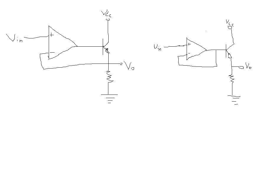
i would like to ask if which of the two is a better buffer? thx

pardon my drawing

80_1163235232.JPG
 

Re: help in opamp

the left one is better,i think.
the voltage of the right one is variable.
 

Re: help in opamp

The left one !!!
It is forming a negative feedback loop, and keeping the Vbe constant even if Vcc is varying and ensure the current in the resistance be same i.e. Vo.

In the right one the voltage at the base will be const. but it is nothing to do with Vcc noise, which may cause varying current and not a const Vo.

-Bharat
 

Re: help in opamp

frozenhell,
The left circuit has the transitor Vbe drop inside the feedback loop, so it's effect sare reduced by the loop gain.
.
Th output of the circuit on the right will be equal to the base-ground voltage minus Vbe, which varies with temperature, and is non-linear with respect to current.
.
Conclusion: Use the left circuit.
Regards,
Kral
 

Re: help in opamp

Use left. You NEVER find right one in products.
 

Re: help in opamp

Use the left. The right has no loading ability as a driver.
 

Re: help in opamp

if there is connection between -Vin and the emmiter node of BJT in the left than Yes use the one on the left... because you than have a feedback action going on
and Vo is stable.... in the one to the right you have a steady current in the collector of the BJT ( as long as you dont change Vin).
 

Re: help in opamp

this is series series topology feedback amplifier..need to find the openloop gain
 

help in opamp

the firsit is good,
 

Re: help in opamp

the output of the left figure is included in the negative feedback loop, while the right does not, so the left one could obtain a stable output voltage.
In fact ,the left one is a basic LDO regulator, the output voltage depends on the input voltage
 

Re: help in opamp

Left one is better for the following reasons


1) Low output impedance 1/A*Gm || R =1/(A*Gm) and for right it is 1/Gm || R

2)High resistance to power supply variations (calculate ,it will be A*Gm*Ro*R) for right it will be Gm*Ro*R

3)Not that sensitive to output change as Vin is fixed for right side but for left it is magnified by A times and fed as negative input to correct that

hence left side will ensure that output is always rigid and with least variations.

thanks to high gain of opamp (Virtual ground )as it ensures output scaling with input and also maintaining that very very robust

Added after 13 minutes:

also there is Vt or Vbe limitation in second one but now in first.

Note : Vbe or Vth(mosfet) does vary with temp and process but for the first one output is almost equal to input . for right it is not consistent and it has Vt limitations
 

help in opamp

the left one. We have the same structure as it, and it work well
 

help in opamp

The left one is a voltage follower (VIN=Vo) with negative feedback regulated by the op-amp.
The right one, ridiculous, nothing for a buffer design as the op-amp is a unity gain buffer and to drive the output n-type BJT. There's no relationship between Vin and Vo provided you DON"T KNOW resistor value and VBE drop and VDD. Ridiculous!
 

Re: help in opamp

The left one is a negative feedback loop. In which the Vout is the same as Vin. So, it not really a buffer, the application is different like in voltage regulator design. The right one actually acts as a buffer (unity buffer). So, the base voltage is the same as the input voltage. The thing is this kind of design is very rare in used and sometime not practical as the common collector itself already behaved as a buffer. So no need the unity gain buffer actually.
 

Status
Not open for further replies.

Similar threads

Part and Inventory Search

Welcome to EDABoard.com

Sponsor

Back
Top