Welcome to our site! EDAboard.com is an international Electronics Discussion Forum focused on EDA software, circuits, schematics, books, theory, papers, asic, pld, 8051, DSP, Network, RF, Analog Design, PCB, Service Manuals... and a whole lot more! To participate you need to register. Registration is free. Click here to register now.
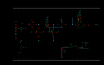
I used an OTA with the PMOS input and the result is the same. When I use VCM the configuration of integrator works, but if I use GND don't.
Using a rail-to-rail OTA, I'll obtain success in to achieve the desired result?
Thanks.
In this case the ICMR of your special OTA topology doesn't contain GND, i.e. if one of the inputs receives GND potential, the OTA doesn't work within its linear range any more.
This, e.g. is the case if you use feedback either directly or via a resistive divider from the output to the inverting input: if your output is unable to get completely down to GND, the OTA feedback loop cannot bring down the inverting input to GND either, hence the circuit gets out of its linear operation range. To avoid this, you'd have to redesign your OTA topology completely.
This site uses cookies to help personalise content, tailor your experience and to keep you logged in if you register.
By continuing to use this site, you are consenting to our use of cookies.