Continue to Site

Welcome to EDAboard.com

Welcome to our site! EDAboard.com is an international Electronics Discussion Forum focused on EDA software, circuits, schematics, books, theory, papers, asic, pld, 8051, DSP, Network, RF, Analog Design, PCB, Service Manuals... and a whole lot more! To participate you need to register. Registration is free. Click here to register now.

Help for soccer substitution board circuit

Status
Not open for further replies.

zawminoo

Advanced Member level 4
Joined
Dec 6, 2005
Messages
105
Helped
4
Reputation
8
Reaction score
1
Trophy points
1,298
Activity points
2,233
Hi Everybody,
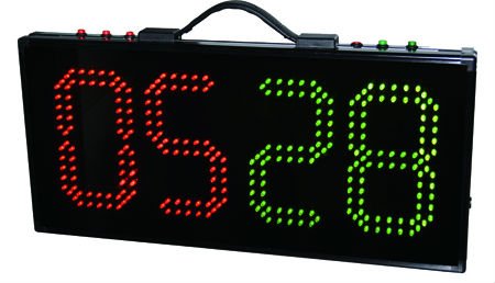
I would like to make a soccer substitution board circuit with LED.
I don't want to use microcontroller.
Pls give me any idea.
Thank!
9799537300_1407193280.jpg
 

It looks as though each segment is made up from 12 individual led's.

You can use the customary IC's (7447, 4511, 4543). However 12 led's are too big a load for one output pin. You'll need to feed each output signal to a transistor/mosfet, which will drive the led's.

The 12 led's will be in series or parallel. Your work will be easier if they are in series. Then they'll need a power supply of 20 V or more.

You'll need to decide whether to light all numerals continuously, or to multiplex them.
 

Each segment though shares the corner LEDs with its adjacent segments. So driving those corner LEDs is going to require some special handling.

Also why don't you want to use a microcontroller to manage the numbers displayed, how do you intend to enter what numbers you are going to display? switches, numbered dials, what?
 
Your right I had to zoom in to see it. That LED array is like an optical illusion. :)
 

You can design this easily around four BCD thumbwheel switches, four 7447 decoders (BCD>7seg.) and 7x4=28 transistors with 12 LEDs per segment in an array so both colours use the same voltage with two 3.7V Lipo Batteries. Extras can be added like a charger jack.

(Added) More thought needs to be given to driver voltage and current. Eg. 7446A can drive open collector 30V@40mA which can be two parallel strings of 6 LEDs per segment giving 20.4V for Green and 13V for Red requiring 2 boost converters slightly higher, but then saving 28 transistors.

12x7x2 =168 pairs of RED(2.2V) & GREEN (3.2V) LEDs with 4x7seg = 28 (Bipolar or MOSFET) switches with selected voltages or current sources. YOu can use a 2x8bit latch if you wish to update the display instantly rather than switch encoded in real-time as you wish. Remember to filter the switches.

For 5mm LEDs consider > Power, Beam Angle, Battery voltage, SMPS, elliptical 5mm Lens diffused or clear or 5mm round or? I would use 34x70deg wide elliptical.

POWER 25W total if all segments 88 88 are on.
Red you need at least 168 x2.2V x 20mA = 8.4W est.
Green for each LED in a segment in series 168x3.4V x20mA = 11.4W

For voltage, I would choose a common denominator voltage for each segment.
e.g. 2 Green is close to 3 Red in Voltage. 2x3.4V=6.8V(grn) ~ 3x2.2V=6.6 (red)
Therefore consider each segment as an array of 4P3S (Red) and 3P4S (green) for an average voltage of 6.7V which is easily derived from 2 LiPo batteries in series.

Max current with "8888" would be:
Red 4P x7seg x2dig x 0.02A =1.12A
Grn 3P x7seg x2dig x 0.02A=0.084A

Hammer driver Darlington's have 7 drivers in a chip could be used or very cheap SMT MOSFETS with 35mOhm resistance.
Better if you use low Vsat or RdsOn to use all of the 7.2V battery range when depleted to 6V. (Red can be obtained down to 2.0Vx3S=6V )
LiPo power should last many games using 7.2V battery with a ~3 Ohm series current limiter for each segment or use a Polyfuse for ~100mA.


Much more thought in making it robust, high efficiency, wide viewing angle and variable brightness can be added.
Much more thought into high quality Elliptical diffused LEDs with over 5000 mcd will be suggested from a good supplier I know.
 

Status
Not open for further replies.

Part and Inventory Search

Welcome to EDABoard.com

Sponsor

Back
Top