Continue to Site

Welcome to EDAboard.com

Welcome to our site! EDAboard.com is an international Electronics Discussion Forum focused on EDA software, circuits, schematics, books, theory, papers, asic, pld, 8051, DSP, Network, RF, Analog Design, PCB, Service Manuals... and a whole lot more! To participate you need to register. Registration is free. Click here to register now.

help for ISO122( isolation amplifier) power supply

Status
Not open for further replies.

zizi110

Member level 1
Member level 1
Joined
Jun 24, 2013
Messages
41
Helped
0
Reputation
0
Reaction score
0
Trophy points
6
Visit site
Activity points
313
Hi guys,
i select ISO122 as isolation amplifier for creating isolation between power stage and micro controller.
the input of ISO122 is DC voltage that varies from 0 to 3 v.
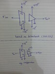
based on ISO122 datashet i must use 4 power supply :(
+15 and -15 for both side.
first question : based upon just sensing DC VOLTAGE in the ISO122 input ,is there any way that just using single supply for every side of ISO122? i means for power side of ISO1222 i just use +15 for VS+ and VS-=0 and for micro side of ISO122 VS+=5V and VS-=0.
 

Attachments

  • 20150223_182243.jpg
    20150223_182243.jpg
    1.8 MB · Views: 240

Sounds like a question that will be answered in the datasheet, isn't it?

It shows a single supply circuit for the input side, using a virtual ground.
 

so i can't use single supply for output side? i was planning to just using single supply for output side that supply of micro controller and output side be the same (5v) from one regulator, is it possible?
how can i create -15v supply for output side?
 

minimal Vs+ to Vs- span is 9V in any case. So +/- 5 would be an option. You can of course use a solution similar to the virtual ground suggestion on output side, but you get a level shifted output which must be downshifted to e.g. fit a 0-5 V ADC range.

It's all about analog design craftsmanship, some power of imagination required.
 
why ISO122?? it's more expensive as much as 3 times compared to AMC 1100. Furthermore AMC 1100 just need a 5v source at each side. you can use small DCR1050505 isolated DC/DC converter or Murata or other companies 5v-5v isolated dc/dc converters.

good luck
 
Hi all,
thanks FvM.
thanks kappa_am for your suggestion, but you know AMC 1100 max input range is about 250mV and that is not enough for my design.
the input of isolator amplifier should be able to varies between 0 to 3V.
any way it was interesting for me that it has same power supply at each side, i searched paya electronic and javan electronic but unfortunately AMC1100 was not available, do you know anywhere for buying it?


regards
 

Hi zizi110,

You may also find TF6664N from Mornsun useful. It works on 5V supply, isolates 0-5V, and also provides a 15V 20mA isolated power supply.

Hope this helps..
Regards,
JayantD
 
use simple voltage divider. I used AMC1200 and 1100 to measure voltages up to 700V.
 

use simple voltage divider. I used AMC1200 and 1100 to measure voltages up to 700V.
Yes. But a buffer amplifier would be required to keep the AMC1x00 accuracy if you drive if from a different source than a low resistance shunt.
 

Yes. But a buffer amplifier would be required to keep the AMC1x00 accuracy if you drive if from a different source than a low resistance shunt.
Hi FvM,
I am afraid I do not find out exactly what your meaning is.
you mean voltage follower in input? there is no need for voltage follower. Just it is needed to keep in mind that input resistance of AMC1x00 is 28kohm. I have implemented some circuit and have checked it with input of sine wave up to 30KHz, and the output followed the input exactly.
 

I believe that the "output followed the input exactly", at least at first sight.

But input resistance is only typically 28 kohm, prone to type and temperature variation. To keep the AMC1x00 accuracy, the source resistance must be respectively low. If you consider e.g. +/- 10% Rin variations, the source resistance must be in a 1k range to limit the additional gain error to 0.5 %. If you can give the voltage divider respecitively low resisrtance, it's no problem.
 
yes you are right. i always had low shunt resistor in my applications. However, there is no data about effect of temperature on input resistance in datasheet. I will check it. maybe the effect of the temperature be ignorable.

Regards,
 

The problem arises if a circuit should keep certain specifications by design, despite of incomplete component data.

Many designs never face a problem although they haven't been strictly calculated, just by chance and because component tolerances are smaller than permitted limits.
 

Status
Not open for further replies.

Similar threads

Part and Inventory Search

Welcome to EDABoard.com

Sponsor

Back
Top