Continue to Site

Welcome to EDAboard.com

Welcome to our site! EDAboard.com is an international Electronics Discussion Forum focused on EDA software, circuits, schematics, books, theory, papers, asic, pld, 8051, DSP, Network, RF, Analog Design, PCB, Service Manuals... and a whole lot more! To participate you need to register. Registration is free. Click here to register now.

help for capacitive sensor interface circuit

Status
Not open for further replies.

malhi

Newbie level 6
Joined
Nov 13, 2008
Messages
13
Helped
0
Reputation
0
Reaction score
0
Trophy points
1,281
Activity points
1,420
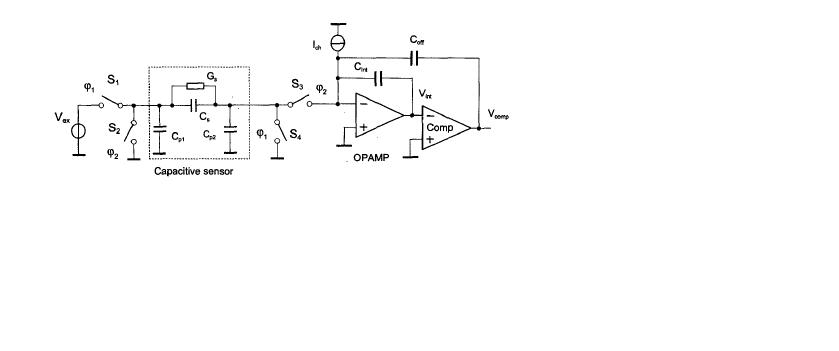
capacitive sensor circuit

hi
i am undergoing through my intership...i have got the job for interfacing circuit for capactive sensor.

i have got the problem, frequency is changing very frequently while dielectric is 1.
in this following fig

https://obrazki.elektroda.pl/32_1251441166.jpg

32_1251441166.jpg
 

sensor site:www.edaboard.com -search

Please add some info as to what frequency change is?
 

capacitive interface circuit

thanx for replying

i am using opamp--OPA2350
comparator--LM339
frequency is varing from --60 to 300 Hz,,

i have to count the pulses, but i am not getting the way out of this how to measure the pulses by this varing frequency
 

capacitor sensor circuit

Sounds like you forgot to mention some important circuit details, e.g. a feedback from the comparator output to the switch control?

However, if you get 60 to 300 Hz depending on the capacitance and the measurement is reproducable, the circuit seems to operate perfectly. If so, what's the problem?

P.S.: If you get chaotical frequencies with constant capacitance, it would be meaningful to reveal the operation pricinciple of the control circuit and to present considerations, why a stable operation should be expected at all.
 

capacitive sensor interface

sorry for that, i have just got the circuit,there is nothing mentioned values for components and my job is to make the controller to count the pulses from its output.

but i have got the doubt in this, if i am keeping the dielectric same(const). then why my frequency is not stable?
 

You didn't clarify at all, where "your frequency" comes from. There's no generator in the circuit.
 

there is a current source of 5-20 mA Output
if i remove the current source there is no effect or change in frequency,variation is constant
 

I also have some doubts regarding this circuit. When simulating, there is no frequency variation(frequency is constant while capacitance is varying). When there is a feedback from comparator to the sensing capacitor,then the frequency is varying. But then what is the use of input voltage source?
Also, it is mentioned that the current source is a controlled one. But actually which voltage/current controls that i don't know.
Please help me.
 

Status
Not open for further replies.

Similar threads

Part and Inventory Search

Welcome to EDABoard.com

Sponsor

Back
Top